Design Guide to Clear Encapsulated Microfluidic Devices
< 5 minute read
The fabrication of a complete, well-functioning microfluidic device requires a combination of basic 3D printing knowledge, careful planning, and iterative design testing. In this design guide for clear encapsulated microfluidic devices, we explore useful tips and techniques to equip users with the right tools to improve their CADing, and achieve the desired 3D printing results.
Tip 01: Know your 3D Printer and 3D Material
The foundation of 3D printing relies on two key components: a 3D printer and a 3D material (or resin). Having a keen understanding of your 3D printer’s capabilities and how they interact with different 3D materials is fundamental to optimizing the success rate of your 3D printed microfluidic devices. This is especially true for devices with sub-100µm (XY) encapsulated channels. Users should know the basics of what each print setting does and be able to adjust them to achieve the best printed results.
At CADworks3D, we developed a simple and systematic approach to determine the optimal print settings for each 3D material we test on our 3D printers. Many 3D material manufacturers will provide recommended print settings. These settings serve as a valuable starting point from which adjustments can then be made. Basic steps are as follows:
- Generate a STL file consisting of 10mm x 10mm x 10mm cubes and print them with the manufacturer’s recommendation.
- Measure the length of the cube in the X and Y directions. If it is less than 10mm, slightly increase the exposure time by 0.5 – 1 second each time. If the length is more than 10mm, slightly decrease the exposure time by 0.5 – 1 second each time.
- If you notice the print is not adhering well to the buildplate during printing, increase the bottom exposure time by 3 – 5 seconds each time. If prints are too difficult to remove from the buildplate, reduce the bottom exposure time by 3 – 5 seconds each time.
For every CADworks3D printer, we have optimized print settings for our line of 3D materials including the Clear Microfluidic Resin. This profile is accessible to every CADworks3D user.
LEARN MORE ABOUT
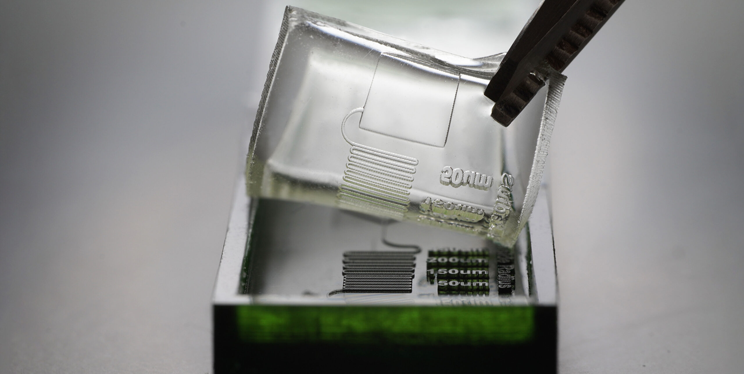
Fabricating Clear Devices with 100µm encapsulated features
with our Clear Microfluidic Resin

Tip 02: Consider Channel Shapes
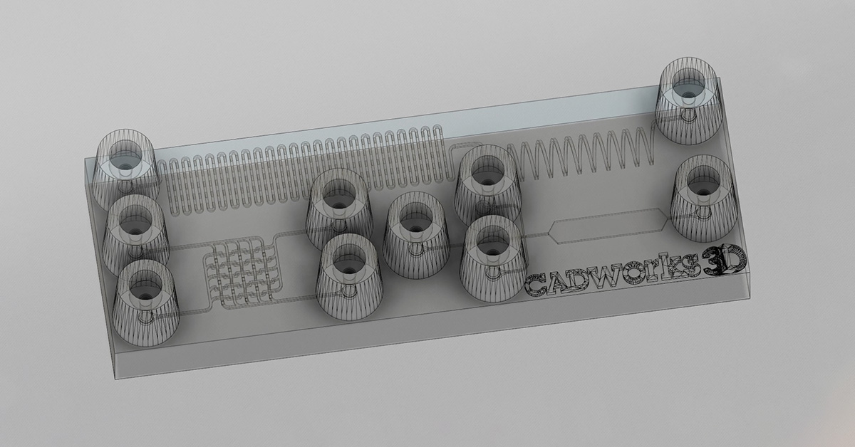
There are three common shapes recommended: circles squares and triangles. The choice of shape largely depends on the size and complexity of your design.
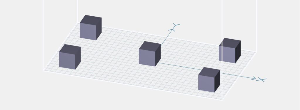
Test printing 10mm x 10mm x 10mm cubes.
Circles are suitable for less intricate designs and channels with a larger diameter.
Squares offer versatility and are suitable for medium complexity
Triangles are ideal for highly intricate designs with small diameter channels
Our recommendation is to start with square channels. You can then adjust the size and shape as needed if the initial design does not yield the desired results.
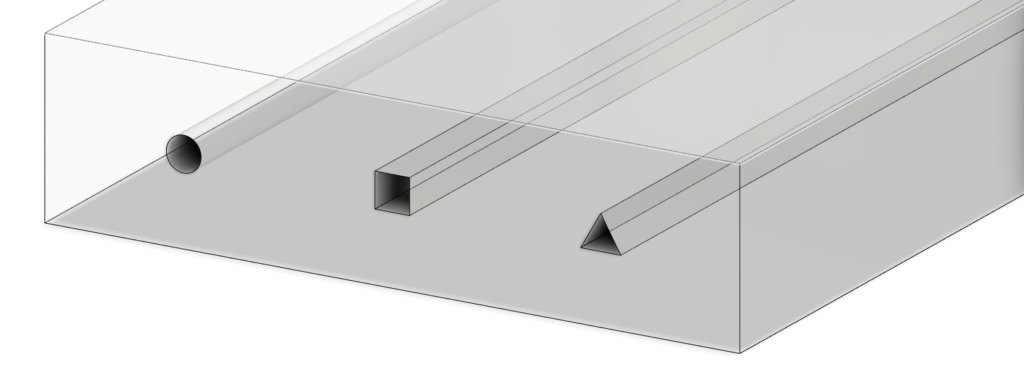
From left to right: a circle, square and triangle channel. Built on the Autodesk Fusion 360
Tip 03: Determine the Optimal Distance between the Channel and the Top of the Device
When designing microfluidic devices with encapsulated features, there are fundamental principles you must adhere to. Among these is the placement of a channel along the Z-axis. Even if you have designed a device with a seemingly perfect channel system, the depth at which the channels sit can significantly impact its functionality. Channels positioned closer to the top of the device tend to exhibit superior functionality.
Encapsulated channels sitting closer to the top of the device go through less printing cycles and are exposed to UV light less. In contrast, channels that sit deeper within the device are exposed to more cycles of UV light, therefore increasing the risk of trapped resin within the encapsulated channels curing. This is especially true for clear materials where light easily passes through to previous printed layers.
Conduct thorough testing on the 3D printer you are working with. This process involves incrementally moving channels closer to the surface of the device to determine the optimal height.
Tip 04: Fillet Channel Edges
One common oversight when building encapsulated channels is failing to fillet edges. Note that filleting applies to the edges of the sketch design, not the actual channel itself.
As you build the sketch for you channel design, identify any lines with sharp edges. These are the areas where fillets should be applied to properly connect the two points, resulting in a seamless and continuous line. This is particularly relevant to square and tringle channels.
Filleting edges ensures your channel flows smoothly and devoid of any obstructions. Such obstructions can significantly affect pressure levels, ultimately resulting in reduced pressure that is essential for filling and clearing the channel properly. As such proper edge filleting significantly impacts the functionality and performance of your microfluidic design.

Channel with a non-filleted edge (left) vs. a channel with a filleted edge (right). Built on Autodesk Fusion 360.
Addressing Common Design Challenges
Even with a robust design process it is not uncommon for 3D prints to encounter setbacks. When issues arise, it is entirely normal to return to the drawing board to address problematic aspects of your design. Over the course of our experience with creating CAD files for microfluidic devices, we identified a few recurring challenges during the design and 3D printing process.
A few we have discussed in this post, including:
- Print settings may not be optimal for a specific design and needs fine-tuning
- The encapsulated channel may not be positioned at a suitable height and get filled in with cured resin
- Imprecise or sharp 90-degree curves that inhibit smooth liquid flow
Other design problems you may encounter are vertices that are not connected properly, or prints that are failing in the same spot each time. If you are experiencing the latter, it is likely that there is an issue with the CAD file, for example a stray pixel.
Finally, the most important tip one should take away from this design guide to creating clear devices for microfluidics, is experimentation and persistence.