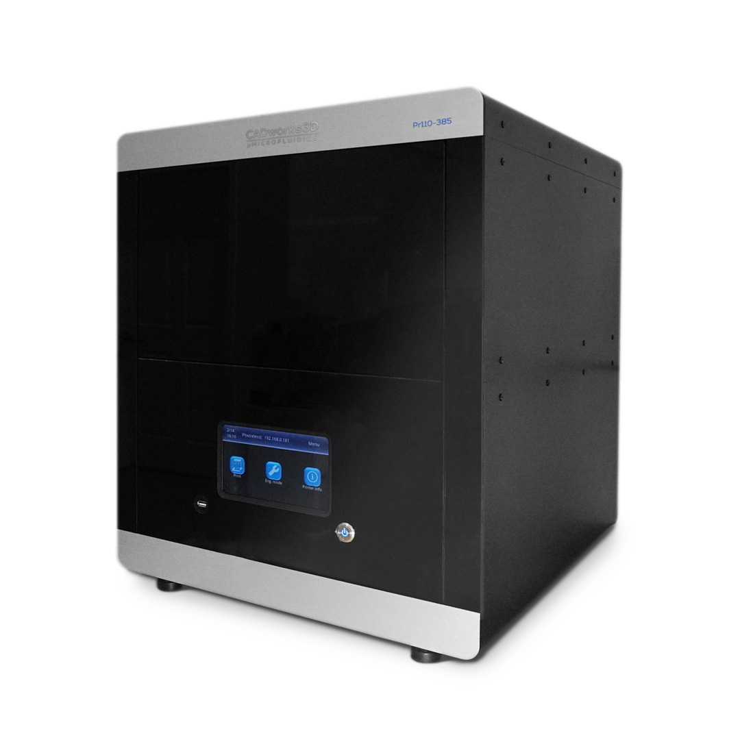
The Tyler Ray team at the University of Hawai’i at Manoa harnesses the CADworks3D Pr110-385 printer and Clear Microfluidic Resin to establish a unqiue class of epidermal microfluidic device, called a ‘sweatainer.’ This device represents a groundbreaking advancement in the collection and analysis of sweat samples.
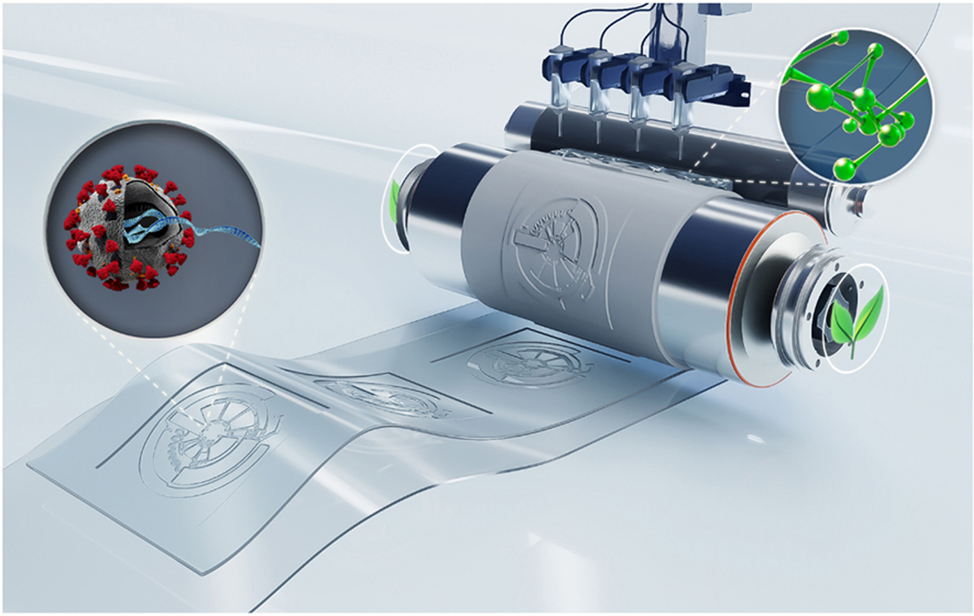
3D printing paves the way for epifluidic devices with a skin-interfaced microfluidic device for sweat capture and analysis
Wu et al. (2023) capitalizes on the recent advances in additive manufacturing to fabricate an epidermal microfluidic device (or epifluidic device), incorporating complex designs that were previously inaccessible.
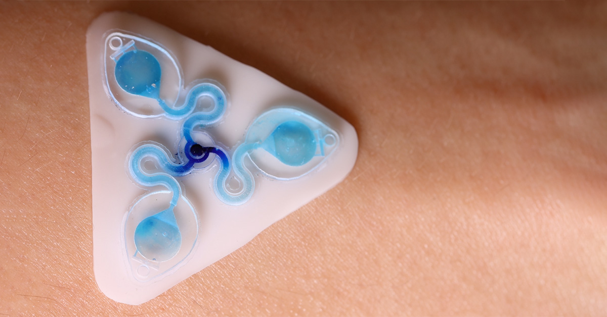
The team has produced the sweatainer, a skin-interfaced wearable system with integrated microfluidic structures, and sensing capabilities to monitor signals arising from natural physiological processes. It enables a new mode of sweat collection termed multidraw. Multidraw facilitates the collection of several independent and pristine sweat samples during a single collection period. The realization of multidraw sweat collection, enabled by customizable design through 3D printing, represents a major step forward in the field of sweat-based analysis.
HOW WAS THE CADWORKS3D SYSTEM USED?
The complete sweatainer system is made up of two primary components: the 3D printed sweatainer device and the epidermal port interface.
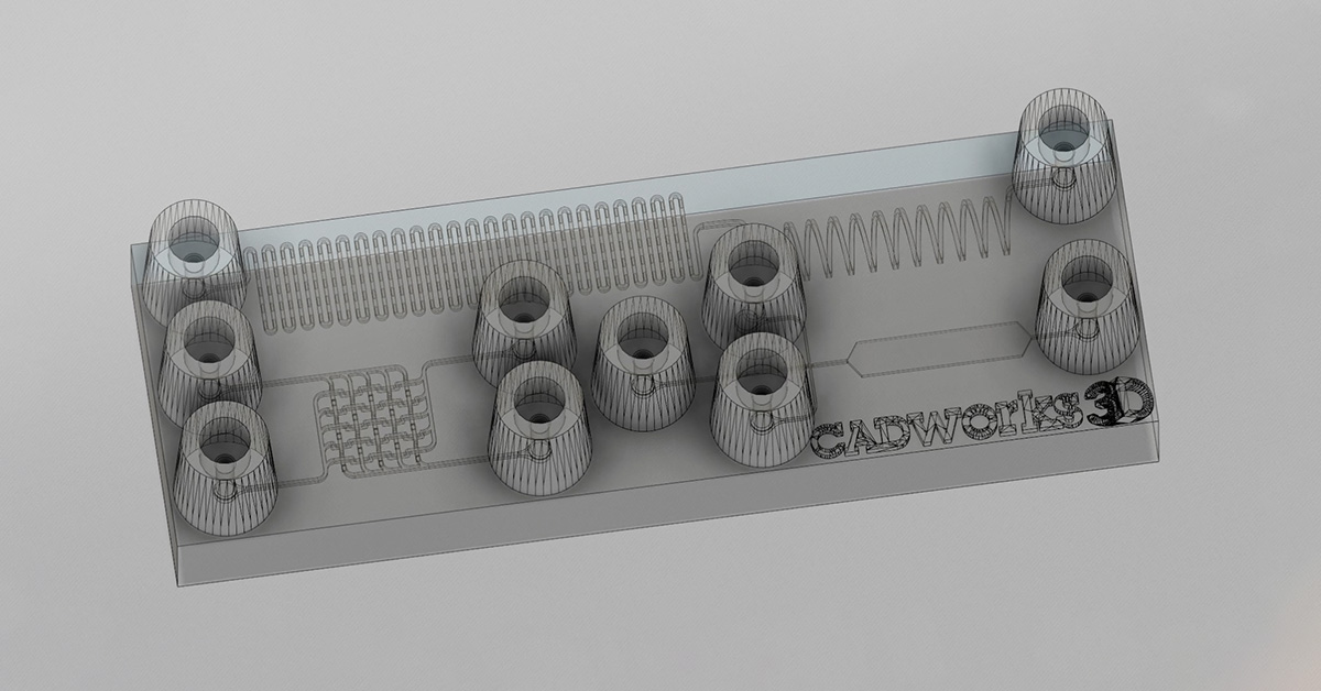
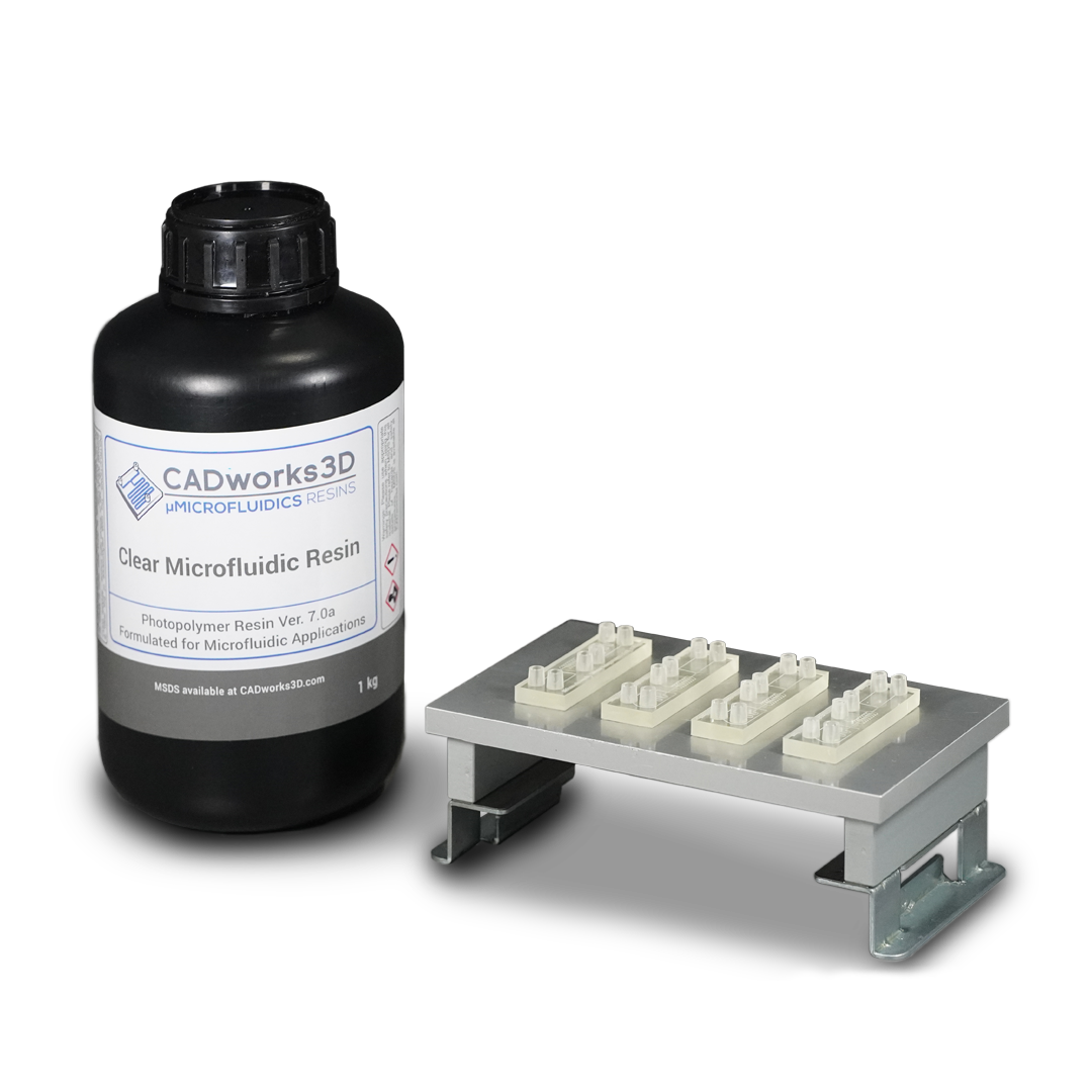
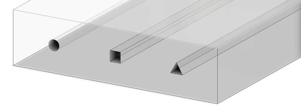
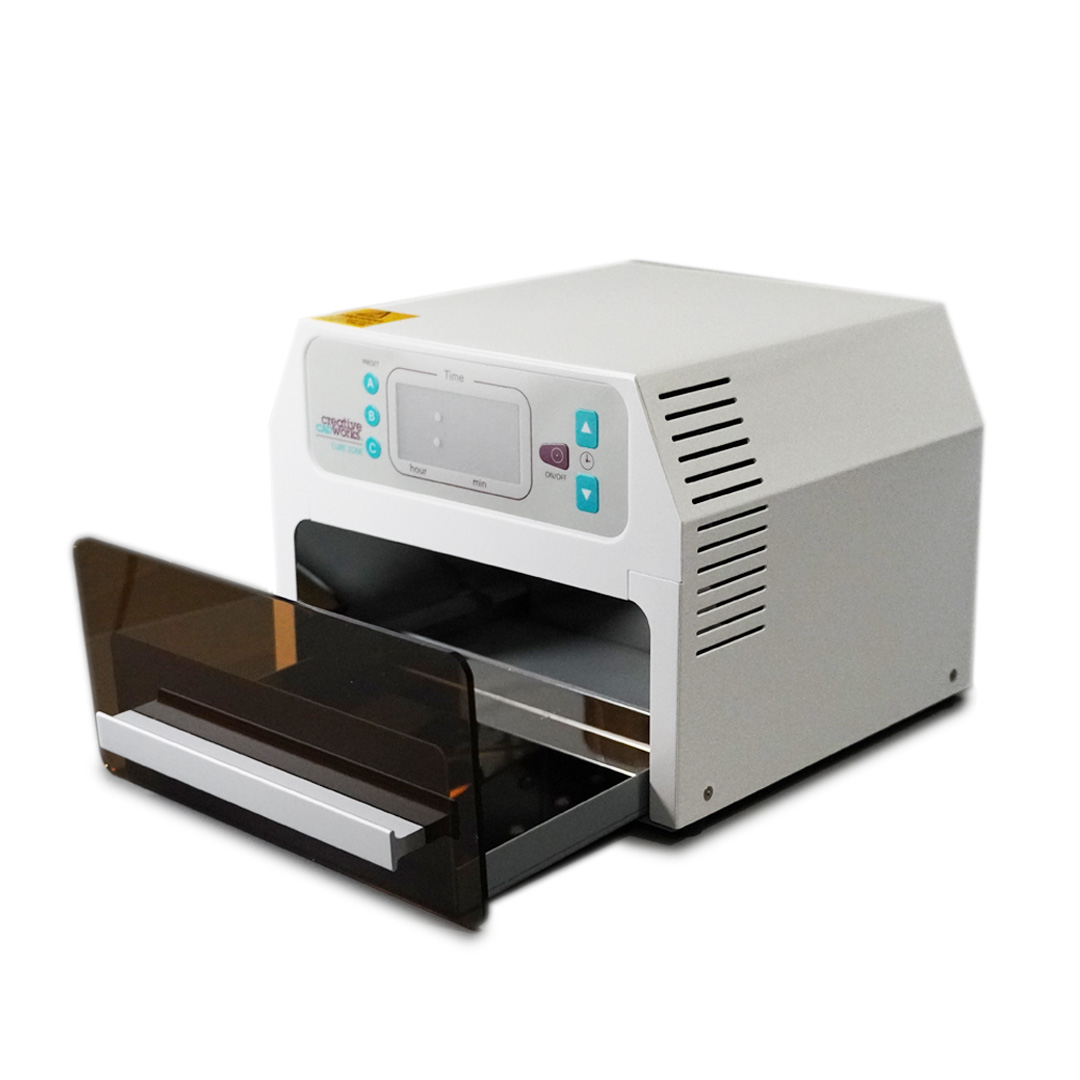
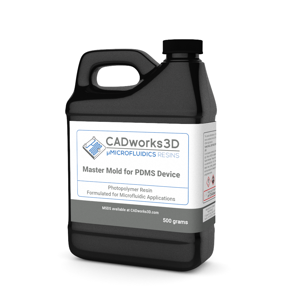
The 3D printed sweatainer was fabricated with the CADworks3D Pr110-385 printer and Clear Microfluidic Resin material. This portion of the device was produced in a single print job. It consists of a microfluidic network of internal channels and valves, as well as unsealed reservoirs with integrated ventilation holes.
Other structural components of the complete device, independent from the 3D printing process, include a layer of PDMS to cover and seal the reservoir, and a biomedical adhesive gasket to bond the the printed device and PDMS layer together.
Together, they form a complete and closed microfluidic structure. Sweat enters the device by a central inlet and flows through a microfluidic channels leading to a series of capillary burst valves (CBVs) and corresponding reservoirs. The CBV at the ingress of each reservoir permits fluid flow only after exceeding a set pressure, thereby enabling time-sequential sweat collection. Integrated ventilation holes (width: 100µm and height: 200µm) on the reservoir eliminates the back pressure that would evolve from trapped air and impede flow. The high-barrier properties of the Clear Microfluidic Resin supports a low sweat evaporation rate with minimal mass loss over a 24-hour period. More details about the fabrication of the sweatainer can be found in the full article.
KEY TAKEAWAYS
Building Complex 3D Geometries
Typical epifluidic devices use soft lithography techniques to build microfluidic components and complex geometries. It requires high-precision molds to form patterned layers of an elastomeric material, commonly PDMS, that when bonded to a substrate yields a complete sealed device.
However, producing such molds with sufficient feature resolution is an expensive and time-consuming process that requires access to specialized environments like clean rooms. Moreover, soft lithography restricts the design space of devices to planar (2D) channel configurations. Although lamination of multiple channel layers can yield elaborate 3D microfluidic networks, each component layer is inherently a planar geometry. Aligning these layers are both time- and labor-intensive. Such requirements result in an elongated iterative design cycle, inequitable access to necessary equipment, and additional challenges for commercial deployment due to incompatibilities with large-scale manufacturing.
3D printing emerges as an attractive alternative to conventional planar (2D) fabrication methods. It is a rapid and cost-effective process, offering powerful capabilities for producing monolithic devices with fully encapsulated 3D structures and spatially graded geometries. As aforementioned, the study show cases this with their sweatainer that incorporates several features including channels, CBVs, reservoirs and ventilation holes.
Wu et al. (2023) identified a number of key benefits as a result of the 3D printing process. For example, the printed CBVs demonstrated finer control over resultant burst pressure in comparison to planar CBVs. In a similar manner, the ability to create spatially graded geometries improved sweat collection efficiency by permitting a continuous transition between the microfluidic channel and reservoir.
Optimization of Print Parameters
The detailed optimization of print parameters of the Pr110-385 3D printer and Clear Microfluidic Resin, played a pivotal role in achieving the key outcomes of this innovative platform.
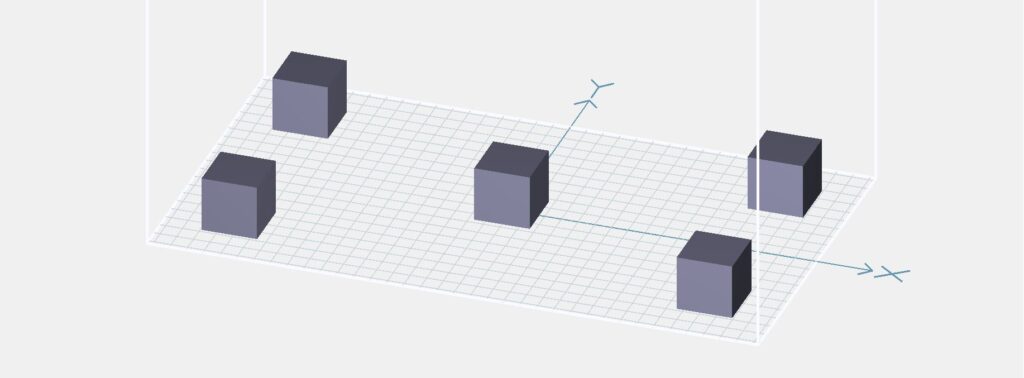
The software provided with every CADwork3D printer offers direct control over a number of print parameters which can be altered for each file. The print parameters can include layer curing times, layer height, dose, and lamp power just to name a few. In the study, the research team systematically optimized the layer cure times and layer height to achieve; robust and accurate channel dimensions, feature sizes below 100µm, and effective mechanical performance.
Moreover, certain CADworks3D printers, including the Pr110-3855 supports variable slicing. Variable slicing enables users to change curing time depending on the layer being printed. This allowed the team to make the most of the Clear Microfluidic Resin, achieving enhanced optical transparency in channels. This transparency was vital for supporting colorimetric analysis using chemical reagents.
CONCLUSION
With the realization of multidraw sweat collection, the sweatainer platform represents a pivotal advancement in the field of sweat-based analytics. Utilizing 3D printing as their key fabrication technology nurtured novel, highly customized geometries and streamlined integration into clinical workflows with it’s rapid iterative design cycles.
