3D printing paves the way for epifluidic devices with a skin-interfaced microfluidic device for sweat capture

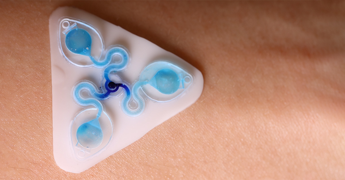
3D printed epifluidic devices called the Sweatainer. Developed by the Ray Research Group.

The Tyler Ray team at the University of Hawai’i at Manoa harnesses the CADworks3D Pr110-385 printer and Clear Microfluidic Resin to establish a unqiue class of epidermal microfluidic device, called a ‘sweatainer.’ This device represents a groundbreaking advancement in the collection and analysis of sweat samples.

3D printing paves the way for epifluidic devices with a skin-interfaced microfluidic device for sweat capture and analysis

Wu et al. (2023) capitalizes on the recent advances in additive manufacturing to fabricate an epidermal microfluidic device (or epifluidic device), incorporating complex designs that were previously inaccessible.

The team has produced the sweatainer, a skin-interfaced wearable system with integrated microfluidic structures, and sensing capabilities to monitor signals arising from natural physiological processes. It enables a new mode of sweat collection termed multidraw. Multidraw facilitates the collection of several independent and pristine sweat samples during a single collection period. The realization of multidraw sweat collection, enabled by customizable design through 3D printing, represents a major step forward in the field of sweat-based analysis.

HOW WAS THE CADWORKS3D SYSTEM USED?

The complete sweatainer system is made up of two primary components: the 3D printed sweatainer device and the epidermal port interface. 

The 3D printed sweatainer was fabricated with the CADworks3D Pr110-385 printer and Clear Microfluidic Resin material. This portion of the device was produced in a single print job. It consists of a microfluidic network of internal channels and valves, as well as unsealed reservoirs with integrated ventilation holes.

Other structural components of the complete device, independent from the 3D printing process, include a layer of PDMS to cover and seal the reservoir, and a biomedical adhesive gasket to bond the the printed device and PDMS layer together.

Together, they form a complete and closed microfluidic structure. Sweat enters the device by a central inlet and flows through a microfluidic channels leading to a series of capillary burst valves (CBVs) and corresponding reservoirs. The CBV at the ingress of each reservoir permits fluid flow only after exceeding a set pressure, thereby enabling time-sequential sweat collection. Integrated ventilation holes (width: 100µm and height: 200µm) on the reservoir eliminates the back pressure that would evolve from trapped air and impede flow. The high-barrier properties of the Clear Microfluidic Resin supports a low sweat evaporation rate with minimal mass loss over a 24-hour period. More details about the fabrication of the sweatainer can be found in the full article.

KEY TAKEAWAYS

Building Complex 3D Geometries

Typical epifluidic devices use soft lithography techniques to build microfluidic components and complex geometries. It requires high-precision molds to form patterned layers of an elastomeric material, commonly PDMS, that when bonded to a substrate yields a complete sealed device.

However, producing such molds with sufficient feature resolution is an expensive and time-consuming process that requires access to specialized environments like clean rooms. Moreover, soft lithography restricts the design space of devices to planar (2D) channel configurations. Although lamination of multiple channel layers can yield elaborate 3D microfluidic networks, each component layer is inherently a planar geometry. Aligning these layers are both time- and labor-intensive. Such requirements result in an elongated iterative design cycle, inequitable access to necessary equipment, and additional challenges for commercial deployment due to incompatibilities with large-scale manufacturing.

3D printing emerges as an attractive alternative to conventional planar (2D) fabrication methods. It is a  rapid and cost-effective process, offering powerful capabilities for producing monolithic devices with fully encapsulated 3D structures and spatially graded geometries. As aforementioned, the study show cases this with their sweatainer that incorporates several features including channels, CBVs, reservoirs and ventilation holes. 

Wu et al. (2023) identified a number of key benefits as a result of the 3D printing process. For example, the printed CBVs demonstrated finer control over resultant burst pressure in comparison to planar CBVs. In a similar manner, the ability to create spatially graded geometries improved sweat collection efficiency by permitting a continuous transition between the microfluidic channel and reservoir.

Optimization of Print Parameters

The detailed optimization of print parameters of the Pr110-385 3D printer and Clear Microfluidic Resin, played a pivotal role in achieving the key outcomes of this innovative platform.

The software provided with every CADwork3D printer offers direct control over a number of print parameters which can be altered for each file. The print parameters can include layer curing times, layer height, dose, and lamp power just to name a few. In the study, the research team systematically optimized the layer cure times and layer height to achieve; robust and accurate channel dimensions, feature sizes below 100µm, and effective mechanical performance.

Moreover, certain CADworks3D printers, including the Pr110-3855 supports variable slicing. Variable slicing enables users to change curing time depending on the layer being printed. This allowed the team to make the most of the Clear Microfluidic Resin, achieving enhanced optical transparency in channels. This transparency was vital for supporting colorimetric analysis using chemical reagents.

CONCLUSION

With the realization of multidraw sweat collection, the sweatainer platform represents a pivotal advancement in the field of  sweat-based analytics.  Utilizing 3D printing as their key fabrication technology nurtured novel, highly customized geometries and streamlined integration into clinical workflows with it’s rapid iterative design cycles.

Design Guide to Clear Encapsulated Devices

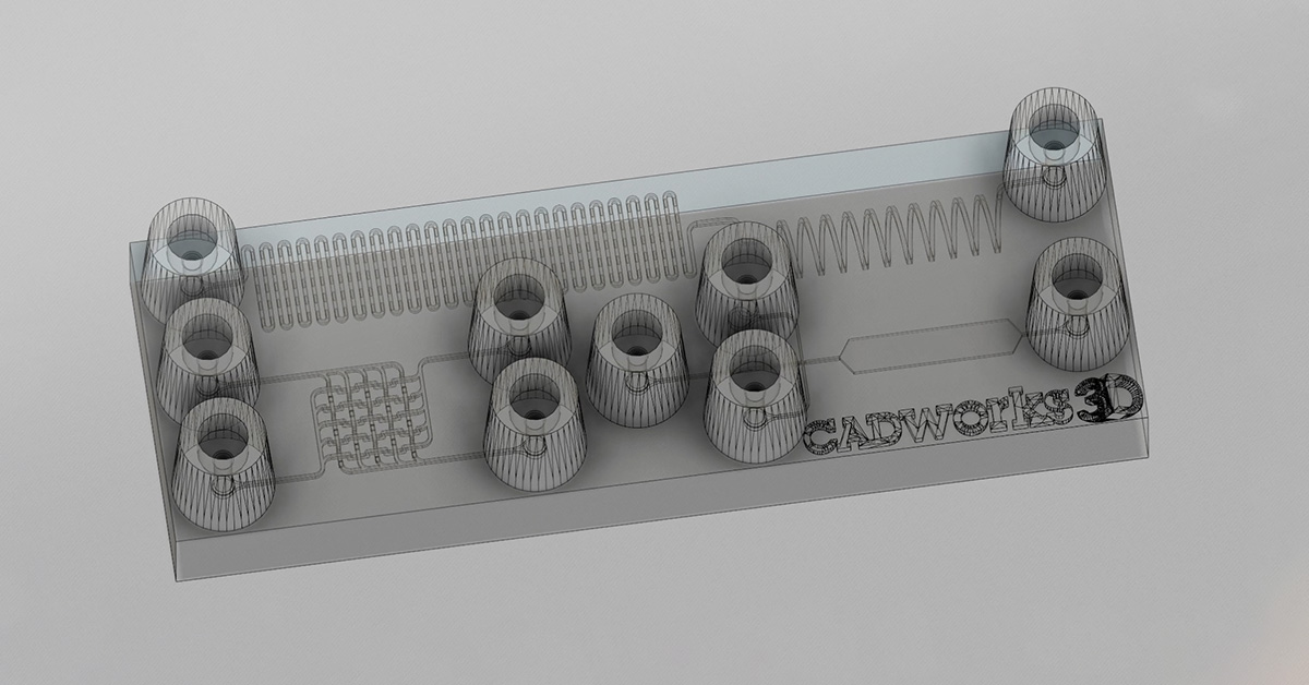
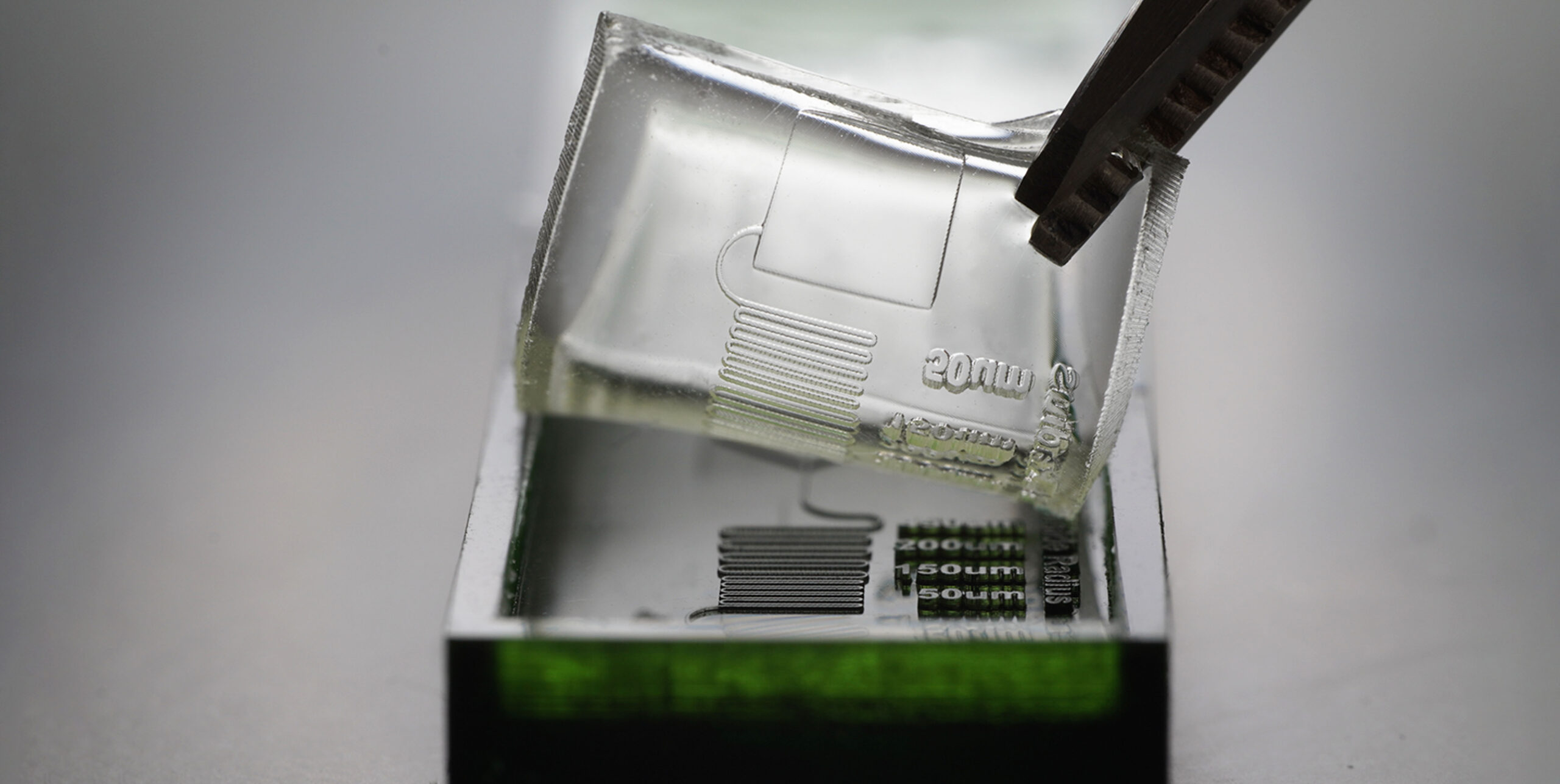
One of many design iterations for a clear microfluidics device with encapsulated channels and features. Designed on Autodesk Fusion 360

Design Guide to Clear Encapsulated Microfluidic Devices

< 5 minute read

The fabrication of a complete, well-functioning microfluidic device requires a combination of basic 3D printing knowledge, careful planning, and iterative design testing. In this design guide for clear encapsulated microfluidic devices, we explore useful tips and techniques to equip users with the right tools to improve their CADing, and achieve the desired 3D printing results.

Tip 01: Know your 3D Printer and 3D Material

The foundation of 3D printing relies on two key components: a 3D printer and a 3D material (or resin). Having a keen understanding of your 3D printer’s capabilities and how they interact with different 3D materials is fundamental to optimizing the success rate of your 3D printed microfluidic devices. This is especially true for devices with sub-100µm (XY) encapsulated channels. Users should know the basics of what each print setting does and be able to adjust them to achieve the best printed results.

At CADworks3D, we developed a simple and systematic approach to determine the optimal print settings for each 3D material we test on our 3D printers. Many 3D material manufacturers will provide recommended print settings. These settings serve as a valuable starting point from which adjustments can then be made. Basic steps are as follows:

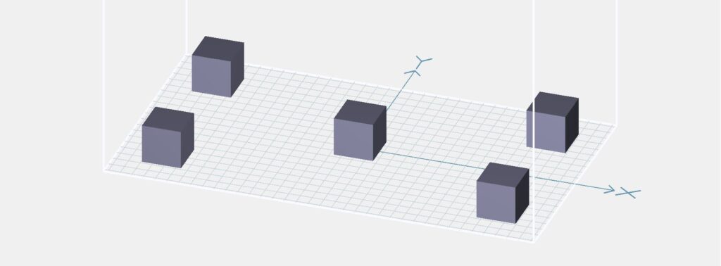
  1. Generate a STL file consisting of 10mm x 10mm x 10mm cubes and print them with the manufacturer’s recommendation.

  2. Measure the length of the cube in the X and Y directions. If it is less than 10mm, slightly increase the exposure time by 0.5 – 1 second each time. If the length is more than 10mm, slightly decrease the exposure time by 0.5 – 1 second each time.

  3. If you notice the print is not adhering well to the buildplate during printing, increase the bottom exposure time by 3 – 5 seconds each time. If prints are too difficult to remove from the buildplate, reduce the bottom exposure time by 3 – 5 seconds each time.

For every CADworks3D printer, we have optimized print settings for our line of 3D materials including the Clear Microfluidic Resin. This profile is accessible to every CADworks3D user.

LEARN MORE ABOUT

Fabricating Clear Devices with 100µm encapsulated features 
with our Clear Microfluidic Resin

Tip 02: Consider Channel Shapes

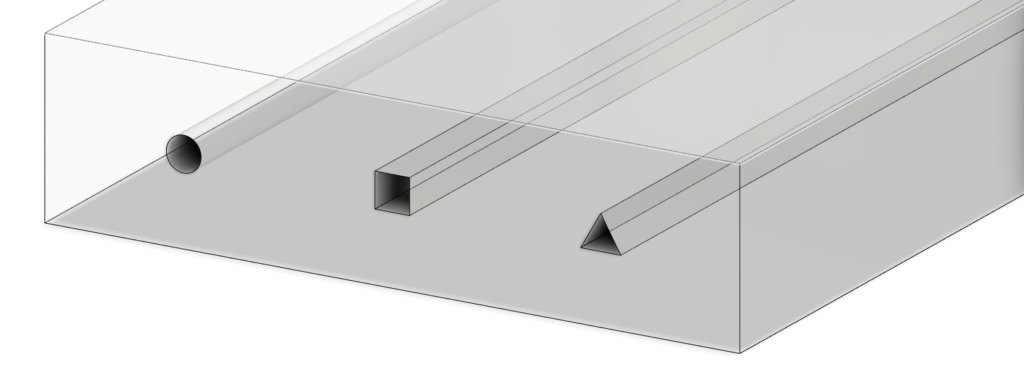
There are three common shapes recommended: circles squares and triangles. The choice of shape largely depends on the size and complexity of your design.

Create optimal print settings by testing how accurately a 10mm x 10mm x 10mm cube 3D prints

Test printing 10mm x 10mm x 10mm cubes.

Circles are suitable for less intricate designs and channels with a larger diameter.
Squares offer versatility and are suitable for medium complexity
Triangles are ideal for highly intricate designs with small diameter channels 

Our recommendation is to start with square channels. You can then adjust the size and shape as needed if the initial design does not yield the desired results.

From left to right: a circle, square and triangle channel. Built on the Autodesk Fusion 360

Tip 03: Determine the Optimal Distance between the Channel and the Top of the Device

When designing microfluidic devices with encapsulated features, there are fundamental principles you must adhere to. Among these is the placement of a channel along the Z-axis. Even if you have designed a device with a seemingly perfect channel system, the depth at which the channels sit can significantly impact its functionality. Channels positioned closer to the top of the device tend to exhibit superior functionality.

Encapsulated channels sitting closer to the top of the device go through less printing cycles and are exposed to UV light less. In contrast, channels that sit deeper within the device are exposed to more cycles of UV light, therefore increasing the risk of trapped resin within the encapsulated channels curing. This is especially true for clear materials where light easily passes through to previous printed layers.

Conduct thorough testing on the 3D printer you are working with. This process involves incrementally moving channels closer to the surface of the device to determine the optimal height.

Tip 04: Fillet Channel Edges

One common oversight when building encapsulated channels is failing to fillet edges. Note that filleting applies to the edges of the sketch design, not the actual channel itself.

As you build the sketch for you channel design, identify any lines with sharp edges. These are the areas where fillets should be applied to properly connect the two points, resulting in a seamless and continuous line. This is particularly relevant to square and tringle channels.

Filleting edges ensures your channel flows smoothly and devoid of any obstructions. Such obstructions can significantly affect pressure levels, ultimately resulting in reduced pressure that is essential for filling and clearing the channel properly. As such proper edge filleting significantly impacts the functionality and performance of your microfluidic design.

Channel with a non-filleted edge (left) vs. a channel with a filleted edge (right). Built on Autodesk Fusion 360.

Addressing Common Design Challenges

Even with a robust design process it is not uncommon for 3D prints to encounter setbacks. When issues arise, it is entirely normal to return to the drawing board to address problematic aspects of your design. Over the course of our experience with creating CAD files for microfluidic devices, we identified a few recurring challenges during the design and 3D printing process.

A few we have discussed in this post, including:

  • Print settings may not be optimal for a specific design and needs fine-tuning
  • The encapsulated channel may not be positioned at a suitable height and get filled in with cured resin
  • Imprecise or sharp 90-degree curves that inhibit smooth liquid flow

Other design problems you may encounter are vertices that are not connected properly, or prints that are failing in the same spot each time. If you are experiencing the latter, it is likely that there is an issue with the CAD file, for example a stray pixel.

Finally, the most important tip one should take away from this design guide to creating clear devices for microfluidics, is experimentation and persistence.

CADworks3D’s Master Mold for PDMS Device Resin empowers a sustainable and low-cost method for mass-producing LoaD device

Sustainable and Scalable roll-to-roll manufacturing platform for PDMS-based LoaD devices

Leveraging the CADworks3D PR110 printer and the Master Mold for PDMS Resin, a team of researchers at Sungkyunkwan University in South Korea paved the way for a scalable and green manufacturing process for polydimethylsiloxane (PDMS)-based microfluidic devices.

CADworks3D's Master Mold for PDMS Device Resin empowers a sustainable and low-cost method of mass producing Lab-on-a-Disc Devices

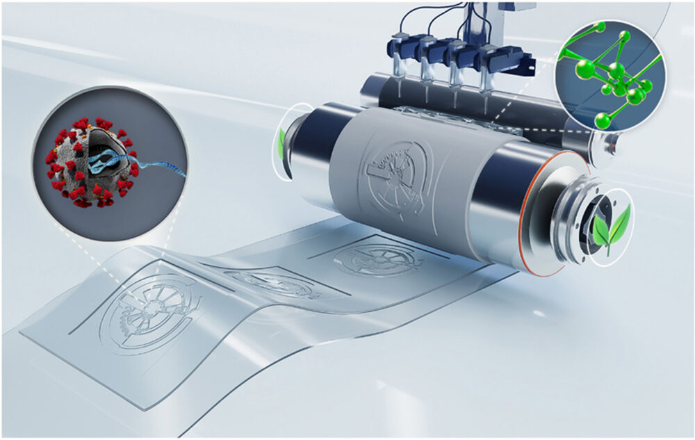
Hoang et al. (2023) have reimagined classic roll-to-roll (R2R) manufacturing technology and transformed it to develop a sustainable R2R additive manufacturing platform for fabricating PDMS-based Lab-on-a-Disc (LoaD) microfluidic devices.

Their innovative approach seamlessly integrates 3D printing and imprinting technology to address traditional molding challenges of LoaD devices. They also introduce a novel PDMS formulation with Ashby-Karstedt catalyst that effectively accelerates the curing time of PDMS at room temperature. In combination, the resulting R2R platform eliminates the need for light and heat sources, significantly reducing energy consumption, the emission of greenhouse gases, and hazardous by-products. As such, this technology demonstrates an efficient and environmentally conscious solution for high throughput PDMS device fabrication.

HOW WAS THE CADWORKS3D SYSTEM USED?

The CADworks3D Pr110-385 3D printer and Master Mold for PDMS Resin were pivotal in creating a multi-depth negative stamp master that incorporated both macro- and micro-sized structures. The team used the 3D printed master mold stamp to cast several positive PDMS replicas. These replicas were then applied to a flexible polymer shim that they wrapped around an imprinting cylinder or roller. The roller would pass over a layer of PDMS that rapidly cures at room temperature, subsequently imprinting the LoaD design into the PDMS.

More details about the R2R 3D printing-imprinting manufacturing platform can be found in the full article.

KEY TAKEAWAYS

Overcoming Traditional Molding Techniques

Hoang et al. (2023) needed a mold fabrication method that could create microfluidic devices with both micro-sized structures and large-volume liquid storage chambers. They found that conventional techniques for fabricating LoaD devices were not ideal. CNC-molds left an extremely rough surface finish and impacted the performance of the device through slow, inaccurate fluid flows and bonding inhibition. Molds that were fabricated using photolithography struggle to create macro-size features. Moreover, due to the need for precise alignment, this technique is time-consuming and labor-intensive. 

3D printing technology addressed several of these limitations. It provided a rapid, low-cost method for fabricating multi-depth master molds with the desired macro and micro features.

Using a Specialized Master Mold Resin for PDMS Application

Not every 3D printing resin is suitable for PDMS applications. Some formulations interfere with the curing of PDMS and require post-printing surface treatments or coatings to ensure a proper cast, or to prevent adhesion of the PDMS to the printed mold.

The Master Mold for PDMS resin is a specialized photopolymer and is formulated for efficiency and ease of use. Post-printing cleaning only requires: rinsing the master mold with isopropyl alcohol or methyl hydrate, drying with compressed air, and curing under a UV light for 40 minutes. PDMS can then be poured directly onto the printed master mold without undergoing any time-consuming and non-replicable surface treatment processes.

High Replication Accuracy

Dimensional analysis of the 3D printed mold, PDMS mold and the R2R imprinted LoaD was performed with an industrial microscope, the Olympus BX53M. Three critical positions in the LoaD design were investigated – the valve, the inlet hole of each chamber and the S-shaped channel. Analysis shows that the master mold features transferred with high accuracy. The lowest variation of structural dimension between the computer aid design (CAD) and the final product was in the range of +-2.7µm. Cross-section images revealed that the multi-depth of the devices were successfully replicated with an accuracy of 99%.

CONCLUSION

The team introduces a state-of-the-art green R2R additive manufacturing platform, and highlights its potential for sustainable and scalable production of PDMS-based LoaD devices. They overcome  two key challenges, related to the fabrication of a multi-depth master mold and a fast-room temperature-curing PDMS. The study emphasizes the significance these technological advancements, where the use of 3D printing technology stands out as a rapid and cost-effective solution to producing master molds for PDMS devices.

READ THE FULL ARTICLE

Room temperature roll-to-roll additive manufacturing of polydimethylsiloxane-based centrifugal microfluidic device for on-site isolation of ribonucleic acid from whole blood

Trung Hoang, Han Truong, Jiyeon Han, Saebom Lee, Jihyeong Lee, Sajjan Parajuli, Jinkee Lee, Gyoujin Cho

3D Printing for Microfluidics: PDMS Devices

3D Printing has several microfluidic applications, a key example being PDMS Device fabrication. 3D Print Master Molds for PDMS with design features that are as small as 50µm

3D Printing for Microfluidics: PDMS Devices

< 5 minute read

Polydimethylsiloxane (PDMS) is the ideal material for soft lithography devices because it has high optical transparency, it is permeable to oxygen and is biocompatibility, which makes it suitable for biological research.   

Master molds are essential for scientific research in the field of PDMS devices. The CADworks3D printer for Microfluidics  with the Master Mold Resin for PDMS Devices is the ideal tool needed to make molds easier, faster and cost effective. Confidently create a variety of iterations of designs and concepts without disclosing IP, not meeting project timelines or budget shortfalls. 

There are several key benefits when producing everything in-house. First of all, your intellectual property is kept within the walls of your company. In addition, once a mold is created in-house, you can make any changes immediately. While outsourcing any projects, there will be a much longer waiting period. For instance, once you receive your mold, you might be required to make additional changes and once again outsource a new file. 

The Master Mold Resin for PDMS Applications is extremely versatile and can print raised channels as fine as 50μm (results based on the M50 printer). The printed mold can be used to cast up to a 2,000 PDMS devices (Statistics provided by the Kelley Lab from University of Toronto).

The Master Mold Resin for PDMS devices has been formulated specifically for microfluidics PDMS devices. The unique features of this material is its high print resolution and being able to cast PDMS directly onto the master mold without the need of a release agent.

The Cadworks3D line of 3D printer and Master Mold Resin for PDMS application are ideal for soft lithography research. The Cadworks3D 3D printer specifications allow it to print fine details required for Microfluidics. At CADworks3D we further calibrate the machine further to meet these requirements. However, a 3D printer is only one part of the equation. The other half would be the resin: 

Master Mold Resin goes hand in hand with the 3D Printer and allows for details as fine as 50μm (model dependent). Meanwhile, other resins on the market cannot be used for fabrications. The Master Mold Resin has been specifically formulated for PDMS applications.