Content Provided By

Apparatus
Rapid fabrication by digital light processing 3D printing of a SlipChip with movable ports for local delivery to ex vivo organ cultures
Megan A. Catterton, Alexander G. Ball, and Rebecca R. Pompano
Abstract
SlipChips are two-part microfluidic devices that can be reconfigured to change fluidic pathways for a wide range of functions, including tissue stimulation. Currently, fabrication of these devices at the prototype stage requires a skilled microfluidic technician, e.g. for wet etching or alignment steps. In most cases, SlipChip functionality requires an optically clear, smooth, and flat patterned surface that is fluorophilic and hydrophobic. Here, we tested digital light processing (DLP) 3D printing, which is rapid, reproducible and easily shared, as a solution for fabrication of SlipChips at the prototype stage. As a case study, we sought to fabricate a SlipChip intended for local de-livery to live tissue slices through a movable microfluidic port. The device was comprised of two multi-layer components: an enclosed channel with a delivery port and a culture chamber for tissue slices with a permeable support. Once the design was optimized, we demonstrated its function by locally delivering a chemical probe to slices of hydrogel and to living tissue with up to 120-µm spatial resolution. By establishing the design principles for 3D printing of SlipChip devices, this work will enhance the ability to rapidly prototype such devices at mid-scale levels of production.
Keywords
SLA printing, resin printing, tissue culture, local stimulation, Two-phase microfluidics
Introduction
The ability to produce microchips easily and with minimal manual assembly, while retaining rapid prototyping capabilities, is highly desirable for pushing microfluidic devices past the first hand-built prototype stage [1–3]. Scaled up fabrication is critical to conducting experiments at moderate scale (dozens of devices) and for propagating such technology to collaborators. In particular, this scale of fabrication would be useful for SlipChips, which are two-phase, reconfigurable microfluidic devices [4–9]. SlipChips usually comprise two planar components that can be “slipped” relative to one another, contain recessed features to hold droplets or streams of aqueous solution, and are separated by a thin layer of oil [4]. SlipChip devices were first developed in the Ismagilov lab [4] as a new technology to perform in low resource settings [5– 7]. The first SlipChips were fabricated from glass plates, which offer ideal surface properties and optical clarity but require wet etching with HF, a hazardous procedure that requires a skilled technician [4,10]. Since then, many different Slip-based designs have evolved, including rotational based Slipdisc and paper-based SlipPADs, to perform a wide range of laboratory processes such as PCR, cell culture and local delivery to tissue slices [8,9,11–18]. Fabrication is especially challenging for novel slip-based devices that have multiple layers per component [9,17]. While injection molding can simplify fabrication at large scale [19], an alternative method is needed to fabricate SlipChips at a moderate scale, while retaining the ability to rapidly prototype.
Any fabrication system for SlipChips must be able to meet four platform requirements, in addition to producing the specific features needed for the intended application. To prevent the aqueous phase from spreading into the oil-filled gap between components, high capillary pressure at the oil-water interface must be maintained. Therefore, the surfaces in contact with 3 the oil layer must be flat and smooth enough to create a gap height between ~1-10 µm across the entire face of the chip [5]. Furthermore, these surfaces must be hydrophobic, and if a fluorinated oil is used [4], a fluorophilic surface is preferred. Finally, for SlipChips that rely on visual alignment or optical detection, the layers must be optically transparent.
Considering these requirements, we reasoned that digital light projection (DLP) 3D printing, which uses UV or blue light to cure photocrosslinkable resins layer-by-layer [20,21], may facilitate SlipChip fabrication and allow for rapid prototyping. This additive method is quickly gaining popularity for fabricating small parts and microfluidic devices, because of the high feature resolution and reproducibility in parts and rapid fabrication speed compared to traditional soft-lithography [3,22–24]. While 3D printing has not been reported previously for SlipChips, two of the four fabrication requirements are already met: We recently described a method for fluorination of a DLP-printed surface based on solvent-based deposition of a fluoroalkyl silane [25], and others have demonstrated transparent prints by using clear resins on a glass surface [26]. The latter process generated a smoother surface with less light scattering.
As a case study for fabrication of a SlipChip by 3D resin printing, we considered a microfluidic movable port device (MP device) previously developed by our lab for local stimulation of ex vivo organ slices [9]. Local delivery devices like this one are used to study intrinsic tissue properties and to screen for potential drugs, by delivering aqueous solutions to specific regions of a tissue sample [9,18,27–30]. Compared to a device with stationary ports, the MP device lessens the amount of user handling of a tissue slice, by repositioning the port below a tissue slice for local delivery with the device. The MP device is a SlipChip that consists of two multilayer components. The bottom component contains an enclosed channel terminating in a 4 single microfluidic delivery port (delivery component), and the top component features a semipermeable tissue culture well (chamber component). In the original hand-built prototype, an extensive fabrication process limited the accessibility and distribution of the MP device to other labs and collaborators [9].
Here, we established an approach to fabricate a 3D printed SlipChip for the first time, using the MP device as a case study. First, we validated the selection of a DLP resin designed for microfluidic devices to meet the optical transparency, surface roughness, surface chemistry, and biocompatibility requirements of the tissue-specific movable port device. Next, the device design was optimized to maximize the functionality of the required ports and channels, while minimizing the fabrication time complexity with DLP printing. The ability of the assembled device to deliver aqueous solutions without leaks into the gap was tested, and finally we tested the ability to stimulate live organ cultures locally and with the position selected on demand.
Material and Methods
Device design, 3D printing, and laser etching
All 3D printed parts were designed using Autodesk Inventor 2018. The CAD files were sliced at 50 µm intervals using MII Utility Shortcut V 3.27 and printed using a CADworks3D M50-405 printer (30 µm xy-resolution, CADworks3D, Toronto, Canada) in BV-007A resin (MiiCraft, via CADworks 3D). The printer settings for the BV-007A resin at a 50-µm slice height was a slow peeling speed, 0.1 mm gap adjustment (unless printing on glass which was 0.27 mm), 1.15 s curing time, 1 base layer, 9.0 s base curing time, 1 buffer layer, and 75% light power. To print parts on glass, a cover glass slide 36 x 60 mm with a thickness of 0.13-0.17 mm (Ted Pella, Redding, CA, USA) was attached to the baseplate by curing a thin layer of BV-007A 5 with a 405 nm UV-light (Amazon, Seattle, WA, USA) [26]. The parts were rinsed with methanol (Fisher Chemical) and post-cured in a UV-light box for 20 s. No additional leaching steps were applied to the printed pieces used in this work. In preliminary experiments, we found that solvent washes at varied temperatures or extended UV light exposure did not substantially improve the biocompatibility of the BV-007A resin. To complete the chamber component, an array of ports with an 80-μm diameter were laser etched (Versa Laser 3.5, Universal Laser Systems, Scottsdale AZ, USA) into the printed BV-007A part, using a power setting of 7% and a speed of 10%.
Fluorination of resin surface and contact angle measurements
Parts printed in BV-007A were silanized using our recently described method [25]. The parts were submerged into a 10% v/v solution of tridecafluoro-1,1,2,2-tetrahydrooctyl trichlorosilane (Gelest Inc., Morrisville PA, USA) in Fluorinert FC-40 (Sigma Aldrich, St. Louis, MO, USA) for 30 min at room temperature. The surfaces were rinsed with 95% ethanol (Koptec) and DI water and finally dried with a nitrogen gun.
Surface air/water contact angles and three-phase contact angles were measured on cubic printed pieces (8 x 8 x 15 mm3 ) using a ramé-hart goniometer (model 200-00, ramé-hart instrument co., Succasunna NJ, USA) and DROPimage Advanced software. For consistency, the smooth, flat face of the cube produced against the polytetrafluoroethylene (PTFE) sheet was tested in all cases; this was also the side of the print that faced the oil layer in the SlipChip. The contact angle was measured in triplicate (3 separate printed pieces per condition), by pipetting one 5-µL droplet of 1x phosphate buffered saline (PBS) (Lonza, Walkersville, MD, U.S.A.; DPBS without calcium or magnesium) onto the printed surface. For three-phase contact angle, 6 the printed cube with a droplet was inverted into a cuvette filled with FC-40 oil containing 0.5 mg/mL triethyleneglycol mono[1H,1H-perfluorooctyl]ether (RfOEG). RfOEG was synthesized in-house as reported previously [9].
Surface profilometry
To assess surface roughness, the root mean square deviation of the surface height of the printed parts were measured with a Zygo optical surface profilometer (Zygo, Berwyn, PA, USA) at the Nanoscale Materials Characterization Facility at the University of Virginia. Cubes of 8 x 8 x 8 mm3 were printed, and surface roughness was measured on all sides, specifically the surfaces printed against the aluminum baseplate or printed against glass, closest to the PTFE sheet at the bottom of the vat, and the sides of the print. As a positive control, a glass microscope slide was also analyzed after plating with 30 nm of Au/Pd by a Technics sputter coater (Technics).
Measurement of curvature of printed pieces
Images of the side profiles of 3D printed 30 x 30 mm prism with various heights (2 – 5 mm) were collected using a Zeiss AxioZoom microscope. The displacement from horizontal due to curvature was manually measured in Zen 2 software.
Animal work and tissue slice collection
All animal work was approved by the Institutional Animal Care and Use Committee at the University of Virginia under protocol #4042, and was conducted in compliance with guidelines of the Office of Laboratory Animal Welfare at the National Institutes of Health (United States). Both male and female C57BL/6 mice aged 19 - 21 weeks (Jackson Laboratory, USA) were housed in a vivarium and given water and food ad libitum. Lymph nodes were harvested from the mice following humane isoflurane anesthesia and cervical dislocation. The tissues were 7 sliced according to a previously published protocol [31]. Briefly, peripheral lymph nodes were collected and embedded in 6% w/v low melting point agarose (Lonza, Walkersville MD, USA) in 1× PBS. After the agarose had hardened, agarose blocks containing lymph nodes were extracted with a 10 mm tissue punch (World Precision Instruments, Sarasota, FL, USA). The blocks were mounted with super glue on a stage and sliced into 300-μm thick sections using a Leica VT1000S vibratome (Bannockburn, IL, USA) in ice-cold 1× PBS. The lymph nodes were sliced at a speed setting of 90 (0.17 mm/s) and frequency of 3 (30 Hz). Slices were cultured in “complete RPMI”: RPMI (Lonza, 16-167F) supplemented with 10% FBS (VWR, Seradigm USDA approved, 6 89510-186), 1× L-glutamine (Gibco Life Technologies, 25030-081), 50 U/mL Pen/Strep (Gibco), 50 μM beta-mercaptoethanol (Gibco, 21985-023), 1 mM sodium pyruvate (Hyclone, GE USA), 1× non-essential amino acids (Hyclone, SH30598.01), and 20 mM HEPES (VWR, 97064–362). Slices of 6% agarose were collected in a similar manner but were stored in 1 x PBS instead of complete media.
Analysis of tissue viability
Prior to assembling the SlipChip, the channel in the delivery component was filled using pressure-driven flow via a Chemyx syringe pump (Fusion 200, Houston TX, USA). A 0.5 mg/mL solution of FITC-conjugated dextran (150-kDa and 70-kDa for agarose and tissue deliveries experiments respectively) was flowed into the channel using a 50 μL Hamilton syringe (model 1705 RN; 26 s gauge, large hub needle) and non-shrinkable PTFE TT-30 tubing (0.012” I.D., 0.009” wall thickness, Weico Wire, Edgewood NY, USA). Next, 500 µL of FC-40 oil containing 0.5 mg/mL RfOEG was pipetted onto the top of the filled delivery component. The chamber component was lowered onto the delivery component, and the two components were clamped together with two binder clips, sandwiching a thin layer of oil between them. The culture chamber on the top of the chip was then filled with 1× PBS. A sample of agarose gel or tissue was placed into the chamber and weighed down using a small stainless-steel washer (10 mm O.D. and 5.3 mm I.D., Grainger USA). The chamber component was manually slipped 9 relative to the delivery component and visually aligned under a microscope to align to a desired port. To initiate a delivery, the syringe pump was turned on at the desired flow rate. After 5 seconds, the pump was turned off and the device was slipped away, to reposition for another delivery or to a reach a closed position. After all deliveries were complete, the sample was removed, and the chamber was flushed with 1× PBS and refilled for the next sample. All delivery experiments were performed at room temperature.
All deliveries were monitored in real time using a Zeiss AxioZoom upright microscope with a PlanNeoFluor Z 1×/0.25 FWD 56 mm objective, Axiocam 506 mono camera and HXP 200 C metal halide lamp (Zeiss Microscopy, Germany), using filter cubes for GFP (Zeiss filter set #38), and Violet Chroma Filter (49021, ET-EBFP2). Images (16 bit) were collected before, during, and after delivery. During deliveries, time lapse images were collected at 1 s intervals. All images were analyzed in Zen 2 software.
Analysis of tissue viability
After alignment of the delivery port to an array port below a 6% agarose slice, with a 5 sec pulse of fluorescein (FITC)-labeled 150-kDa dextran was delivered to the slice at flow rates ranging from 0.2 to 1 μL min−1 (n = 3). After delivery, the device was slipped prior to imaging, to avoid the fluorescent signal from the underlying channel. Delivery width was determined from image analysis as previously described [30]. Briefly, line scans were drawn radially across the delivery region, and the background autofluorescence of the resin was subtracted. The data was fit to a Gaussian curve in GraphPad Prism version 8. The width was defined as 2 standard deviations of the Gaussian curve.
To fit the curve of the spread of analyte with respect to time, we used the previously published analytical model [9]. First, we considered the volume delivered per unit time as described by a cylinder
Parts printed in BV-007A were silanized using our recently described method [25]. The parts were submerged into a 10% v/v solution of tridecafluoro-1,1,2,2-tetrahydrooctyl trichlorosilane (Gelest Inc., Morrisville PA, USA) in Fluorinert FC-40 (Sigma Aldrich, St. Louis, MO, USA) for 30 min at room temperature. The surfaces were rinsed with 95% ethanol (Koptec) and DI water and finally dried with a nitrogen gun.
Surface air/water contact angles and three-phase contact angles were measured on cubic printed pieces (8 x 8 x 15 mm3 ) using a ramé-hart goniometer (model 200-00, ramé-hart instrument co., Succasunna NJ, USA) and DROPimage Advanced software. For consistency, the smooth, flat face of the cube produced against the polytetrafluoroethylene (PTFE) sheet was tested in all cases; this was also the side of the print that faced the oil layer in the SlipChip. The contact angle was measured in triplicate (3 separate printed pieces per condition), by pipetting one 5-µL droplet of 1x phosphate buffered saline (PBS) (Lonza, Walkersville, MD, U.S.A.; DPBS without calcium or magnesium) onto the printed surface. For three-phase contact angle, 6 the printed cube with a droplet was inverted into a cuvette filled with FC-40 oil containing 0.5 mg/mL triethyleneglycol mono[1H,1H-perfluorooctyl]ether (RfOEG). RfOEG was synthesized in-house as reported previously [9].
To assess surface roughness, the root mean square deviation of the surface height of the printed parts were measured with a Zygo optical surface profilometer (Zygo, Berwyn, PA, USA) at the Nanoscale Materials Characterization Facility at the University of Virginia. Cubes of 8 x 8 x 8 mm3 were printed, and surface roughness was measured on all sides, specifically the surfaces printed against the aluminum baseplate or printed against glass, closest to the PTFE sheet at the bottom of the vat, and the sides of the print. As a positive control, a glass microscope slide was also analyzed after plating with 30 nm of Au/Pd by a Technics sputter coater (Technics).
Images of the side profiles of 3D printed 30 x 30 mm prism with various heights (2 – 5 mm) were collected using a Zeiss AxioZoom microscope. The displacement from horizontal due to curvature was manually measured in Zen 2 software.
To fit the curve of the spread of analyte with respect to time, we used the previously published analytical model [9]. First, we considered the volume delivered per unit time as described by a cylinder

where w [μm] is the width (diameter) of the delivery, h [μm] is the height of the slice, Q [μL/min] is the volumetric flow rate set by the pump, and Δt [sec] is the length of time of delivery. Solving for width gives Eq. 2:

Delivery to lymph node tissue
The device was assembled and a lymph node slice was placed onto the chamber. A 5 second pulse of FITC-labeled 70 kDa dextran was delivered at a flow rate of 0.25 μL min−1 . After the first delivery, the device was repositioned and another delivery was performed. This was repeated for four different slices and with slight variations on the number of deliveries on three separate occasions.
Results and Discussion
Design goals for a 3D printed SlipChip with movable ports
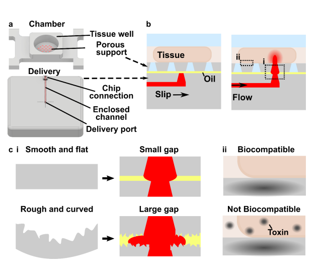
The movable port device consisted of two components: a chamber to hold a tissue slice with a porous support in the form of a port array, and a delivery component with an enclosed channel with a small terminating port (Figure 1a). To operate the device, the delivery port must be aligned with a port in the array above, and pressure driven flow causes a delivery to the tissue in the chamber (Figure 1b). Before a MP device could be rapidly fabricated by DLP printing, there were two major challenges to be addressed (Figure 1c). The first challenge, applicable to any 3D printed SlipChip, was to have a small gap height between the printed parts to prevent leaking into the oil layer during delivery. To achieve a small gap height, the two surfaces closest to the oil gap must be both smooth and flat across the width of the component (30 mm) (Figure 1c). Flatness can be challenging because photocurable resins shrink when crosslinked, inducing mechanical stress that warps the print if not addressed in the print design [33]. Furthermore, an array of microscale ports and enclosed channel had to be integrated in a manner compatible with commercial 3D printers [34], without disrupting the flat surface. The second challenge, specific for biological applications, was biocompatibility of the printed resin with tissue slices housed in the delivery component (Figure 1c). The question of resin toxicity is of great interest to the microfluidics community and is still under active investigation [26,35,36].
Design goals for a 3D printed SlipChip with movable ports
Before designing the microfluidic device, we first selected and validated a resin for its suitability for the intended use in the SlipChip. We chose to use BV-007A resin because of its ability to generate microfluidic devices with high feature resolution [37,38]. First, we addressed the surface roughness and optical transparency of the DLP printed parts. While the polymeric 13 surface would never be as smooth as glass, prior SlipChips have included microposts to set a defined gap height, e.g. of 2 µm, between two glass components [5]. Therefore, we hypothesized that surface roughness ≤ 2 µm would provide an acceptably small gap height. Surface roughness was expected to differ across the various faces of a printed piece, e.g. the bottom that is printed against the baseplate or against glass, the sides of the print, and the top that prints in contact with the PTFE sheet lining the vat (Figure S1a). As expected, optical profilometry showed that the surface printed against the rough aluminum baseplate and the sides of the printed piece were rough, with RMS (root mean square of surface height) > 3 µm (Figure 2a). The polymeric faces printed against glass and PTFE were much smoother, with RMS ≤ 0.3 µm (Figure 2a). For reference, glass itself had a surface roughness of 5 ± 0.5 nm (n=3). From these data, we concluded that the print for a SlipChip must be oriented such that the surfaces intended to contact the oil gap are printed against glass or the PTFE sheet. Additionally, we also tested for optical transparency, which was desirable for visual alignment of channels and ports in the SlipChip. As previously described [26], printing against glass provided optical transparency, whereas printing against the rough aluminum baseplate yielded an opaque sample (Figure 2b).
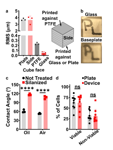
Figure 2: Identification of conditions to ensure suitable surface roughness, optical transparency, surface chemistry, and biocompatibility of the BV-007A printed parts. (a) The root mean square (rms) height of surfaces printed against a micro-milled aluminum baseplate, the side of the print, the final print layer closest to the PTFE vat bottom, or printed against a glass slide (n=3, mean ± Std Dev). (b) Photos of clear resin parts printed on glass or on the micro-milled aluminum baseplate, showing the optical clarity of the former. (c) Three-phase contact angles of a droplet of phosphate buffered saline on a printed part in fluorinated oil or in air, measured before (not treated) and after fluoro-silanization of the part. Two-way ANOVA turkey’s multiple comparison test, n=3, mean ± Std Dev, **** p < 0.0001. (d) The percent of viable (Calceinhigh, 7-AADlow) and nonviable (7-AADhigh) cells after 15 min exposure to a 3D printed part or a plate control (n=9, mean ± Std Dev). Two-way ANOVA turkey’s multiple comparison test, ns indicates p > 0.05.
To prevent spreading of aqueous solution between the components in the oil gap, the surface chemistry of the chip must be fluorophilic and hydrophobic where it contacts the oil phase. While the BV-007A resin yields parts that are moderately hydrophilic, we recently described a method for fluoroalkyl silanization for SLA resins [25]. Here, this method was applied to silanize 15 the BV-007A, and we confirmed that silanization not only increased the three-phase contact angle of a 1x PBS droplet resting on the surface in air, but also when immersed in FC-40 oil (Figure 2c). The water/oil/resin contact angle of > 115° indicated a highly hydrophobic surface [9].
Finally, as the MP Device was intended to be used with live organ slices, we sought to identify conditions in which tissue viability was not affected by the BV-007A printed pieces. Ex vivo slices of lymph node tissue were used in these experiments, as we have previously characterized local delivery to such tissues [9,30]. During use of the movable port device, the tissue slice is in contact with the material only for a short period, i.e. < 5 min for alignment and seconds for the delivery. Preliminary experiments showed that multi-hour physical contact of primary cells with parts printed in BV-007A was cytotoxic (data not shown). Therefore, we restricted this study to an exposure period of 15 min, which represents an upper limit on the time spent in contact with the resin during use of the device. Tissue viability after 15-min exposure was comparable to that of off-chip controls (Figure 2e and S2). We and others continue to work to identify a resin or a post-print treatment strategy that provides biocompatibility with tissue for longer time periods, while still maintaining with the high print resolution of BV-007A [26,35,36,39].
Optimizing the design and printability of the delivery component
Having identified the material and conditions for SlipChip function, we turned to designing the components of the movable port device. The delivery component required three key features to be printed while maintaining a smooth, flat surface: an interior channel, a delivery port, and an inlet (Figure 3a). Additionally, alignment markers (small inset wells on the top of the 16 component) were included in the design to aid in visual alignment of the device when delivering to opaque tissues. Although it is common practice to print at angle to achieve higher resolution for interior channels (Figure S1b, angled) [40,41], the requirement for smoothness dictated that the design be printed horizontal relative to the baseplate, such that the gap-facing surface was printed against PTFE (Figure S1b, flat). In addition, the requirement for a flat profile to minimize gap height meant contending with shrinkage and associated deformation during photocrosslinking [42]. In addition to rounding the sharp corners, we found that increasing the thickness (z) of the printed part was required to minimize mechanical stress during printing for a part with a 30 x 30 mm footprint [42,43]. The thickness of the print was varied from 2 to 5 mm, and the delivery component required at least 5 mm thickness to prevent the part from curling (Figure 3b,c).
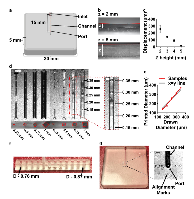
Figure 3: Optimization of the printability of the delivery component of the movable port device. (a) AutoCAD inventor drawing of the delivery component. (b,c) Print warping was minimized by increasing the thickness (z) of the print, analyzed from size-view images (b) and quantified in (c) as the measured displacement of the center of the print from horizontal (mean ± Std Dev, n=3). (d) A top-down image of printed test piece used to determine minimum printable channel and port dimensions. Channel side length varied from 0.25 to 1 mm; cross-sectional shape was diamond or square. The top of each channel included printed ports of 0.15 to 0.35 mm diameter, shown in the inset. (e) Printed diameter of port versus drawn dimension (mean ± Std Dev, n=8); linear fit yielded y = 1.2x – 51. The black line shows y=x, for reference. (f) A test piece used to optimize the inlet connection to fit a PTFE tubing with the tightest connection. (g) Image of the 18 optimized delivery component, with the channel filled with red food dye. Inset shows a micrograph of the delivery port with alignment markers. Scale bar 0.5 mm.
Having optimized the print geometry and overall dimensions of the piece, next, the design of the enclosed channels and ports were optimized to minimize the channel cross-section while retaining printability (Figure 3d). We share these details to aid other researchers who are also working at the limits of the resolution of the printer. To reduce blockage during printing, the channel was positioned close to the top of the part to minimize UV-exposure from subsequent layers, which is a particular issue for transparent resins. Additionally, the length of the channel was minimized (15 mm), because longer channels were more difficult to clear of uncrosslinked resin through the small terminating delivery port. To minimize reagent volume during use, we minimized the cross-sectional area of the channel. In a test piece printed with a series of 15-mm channels of varied cross-sectional size and a square or diamond shape, the minimum crosssection that remained open was 0.5 x 0.5 mm in both shapes (Figure 3d). The square was selected over the diamond shape in order to minimize the horizontal width the channel during optical imaging of the device. The diameter of the delivery port was optimized in the same test piece, with a series of ports of varied diameter atop each channel (Figure 3d, inset). All ports with diameter ranging from 0.15-0.35 mm were successfully printed, with close fidelity to drawn dimension (Figure 3e). The smallest printable port was 138 ± 9 µm (drawn diameter 0.15 mm); ports drawn smaller failed to print (data not shown). Finally, we designed a simple press-fit female port to ensure a snug fit with the microfluidic tubing at the inlet (0.78 mm OD PTFE tubing), by printing mock inlets of 0.76 – 0.87 mm drawn diameter (Figure 3f). A 0.80 mm drawn diameter port was determined to give a snug fit with the tubing. In summary, utilizing a design with all the optimized conditions (0.8 mm inlet, 0.5x0.5 mm square channel cross-section, 19 150 µm drawn delivery port) yielded a flat and smooth 3D printed delivery component with a simple inlet and an enclosed channel that terminated in a small delivery port and could be reproducibly printed (Figure 3g).
Optimization to minimize port size and preserve optical transparency of the chamber component
The top component of the MP device included a chamber to hold tissue samples in media, with a permeable support at the bottom for delivery of fluid from below. Based on our prior work, the ports in the chamber component needed to be in the range of 70-110 µm, i.e. large enough to minimize flow resistance and small enough to create a localized delivery [9]. The support needed to be transparent for visual alignment, and the requirement for smoothness meant that the bottom of the chamber component needed to be printed against glass or the Teflon vat.
We originally tested a one-step fabrication method for this component, by embedding a membrane or mesh support into the part during 3D printing or by directly printing the port array (Figure 4a and b). We found it simple to embed a nylon or metal mesh in the component by adhering it to the baseplate or glass prior to printing (Figure 4a, Figure S3). Unfortunately, due to resin shrinkage during polymerization, the mesh did not remain taut, preventing its use in the SlipChip. Next, we attempted to directly print the small ports in an array (Figure 3b), but it was challenging to meet the requirements for both small port size and transparency. Orienting the port array against glass on the baseplate proved unfeasible due to the required overexposure of the first layers of the printing, which lowered the spatial resolution in these layers. On the other hand, orienting the port array as an overhang generated ports with an acceptable diameter (~110 µm), but the unsupported overhang led to stretching and distortion, which reduced transparency (Figure 4b).
Since fabricating the port array in a single step proved challenging, we elected to use a twostep process (Figure 4c). First, the chamber component was 3D printed with the solid bottom of the chamber well (200-µm thick) oriented against the glass. Second, a CO2 laser was used to etch a port array into the bottom of the chamber. The laser-etched ports had a diameter of 81 ± 2 µm (n=74), well within the acceptable range, and the entire array was etched in < 1 min. Additionally, unlike the accumulation of melted plastic observed when laser etching acrylic [9], there was no deformation of the BV-007A polymer during laser etching on either side of the chamber components (Figure S4), thus minimizing gap height in the SlipChip. The component was sufficiently transparent for visual alignment. Thus, this straightforward fabrication strategy produced a flat, smooth, monolithic part with a well-defined port array, ready for integration into the final SlipChip (Figure 4d and e).
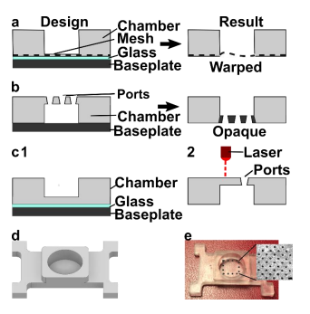
Figure 4: Optimization of the fabrication strategy for a chamber with a microporous bottom. Three fabrication strategies were tested: (a) incorporating a mesh at the bottom of the device by adhering it to the glass-covered base plate during printing, (b) directly printing ports, and (c) laser etching the ports after printing. (d, e) The optimized design of the chamber component 21 shown as an AutoCAD inventor drawing and the 3D printed and laser-etched piece. Inset: Micrograph of the ports etched into the chamber. Scale bar 0.5 mm.
The assembled 3D printed SlipChip delivers fluid without leakage into the gap
Having fabricated both components, we assembled the 3D printed SlipChip (Figure 5Error! Reference source not found.a and b) and tested its ability to perform local deliveries with leakage of aqueous solution into the oil-filled gap, a critical design goal. To assemble the device, the microchannel in the delivery component was filled with aqueous solution, and the chamber component was lowered on top while carefully sandwiching a layer of immiscible oil in between. To test that the aqueous solution did not leak into the oil gap during use, the delivery port was aligned with a port in the array, and a short pulse of fluorescent dextran solution was delivered to an agarose slice through each of three different array ports (Figure 5c). During and after each delivery, fluorescent and brightfield imaging were used to visually inspect the gap area for the appearance of an interface between aqueous and oil phases, which would indicate a leak. No such interface was observed in 3 separate chip assemblies (9 out of 9 deliveries), indicating a robust capillary-pressure-mediated barrier to leakage
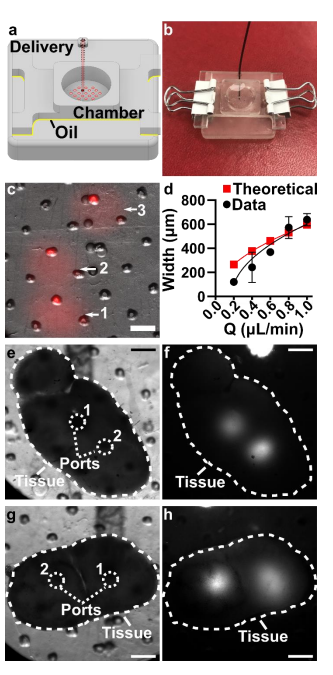
Figure 5: Demonstration of local delivery to slices of hydrogel and live tissue. (a) A schematic and (b) an image of the assembled two-component device, with red solution filled into the delivery channel for visualization. (c) Image after three deliveries of fluorescent dextran (red) to a slab of transparent agarose. Scale bar 500 µm. Numbers indicate the order of the sequential deliveries. Overlaid fluorescent and brightfield data. (d) Plot of delivery width as a function of flow rate (mean ± std dev, n=3). Experimental data (black circles) were fit with a square root function, y = 663√x − 0.178, R2= 0.85. Red squares indicate theoretical prediction (Eq. 2). (eh) Images showing multiple deliveries to replicate tissue slices. (e, g) Brightfield image of the slice of lymph node tissue (outlined in dashed while line) in the assembled device prior to delivery. The ports used for sequential deliveries (white dotted lines) are indicated, with the 23 order of delivery numbered. Scale bar 500 µm. (f, h) Fluorescent image after two deliveries of FITC-labeled dextran (white signal) to the live tissue slice.
Validation of local delivery to hydrogel and tissue slices on the 3D printed chip
Finally, we tested the device’s capability to target sub-structures in gels and tissues via sequential deliveries with high spatial resolution. First, we measured the delivery widths of a model probe, FITC-labeled 150-kDa dextran, delivered in 5-sec pulses to 6% agarose, a model 3D culture material, as a function of flow rate (Figure 5d). The device was slipped between each pulse to select a new delivery location, taking advantage of the mobility of the SlipChip. As expected, the width of delivery increased with flow rate, and matched well with the predictions from Eq. 2, particularly at faster flow rates. At the lowest flow rate, deliveries were achieved as small 120 µm, which is the highest spatial resolution we have reported, and is small enough to target tissue substructures in the lymph node and other tissues [9,30]. Finally, we tested local delivery to live lymph node tissue by using the 3D printed device to deliver multiple times to single tissue slices, again in locations selected on-demand by slipping. Since the tissue is opaque, the alignment of the ports relied on the alignment markers incorporated on the delivery component. Distinct regions within lymph node slices were successfully targeted for local delivery, including, e.g., close together through adjacent ports (Figure 5e,f) or to two different lobes of the lymph node slice. (Figure 5g,h).
Conclusions and Outlook
This paper describes the requirements and fabrication strategy to achieve 3D-printed SlipChips for the first time, and demonstrates 3D printing of a SlipChip device with a movable port for local stimulation of organ cultures as a case study. After optimization, DLP 3D printing 24 produced smooth (RMS ≤ 0.3 µm), flat surfaces that were chemically modified for fluorination. The resin parts were biocompatible with the short term (< 15 min) exposures needed for local delivery to tissue slices. The delivery component was designed to be printed in a single step and contained an inlet, enclosed channel and small (138 ± 9 µm) terminating delivery port. The chamber component was produced via 3D printing followed by laser etching, which provided a monolithic culture chamber with an array of 81 ± 2 µm diameter ports at the bottom, while maintaining a smooth, flat interface for slipping. The device was able to perform multiple slipping and delivery steps without leakage in between the components. The spread of the delivery was dependent on the rate of pump-driven fluid flow, and the resolution was sufficient to target sub-structures in multiple locations in a tissue slice.
We anticipate that this DLP 3D printing fabrication method will enable the polymeric SlipChips, and in particular the movable port technology, to become accessible to other labs, by greatly simplifying the fabrication steps, materials, and time. Continued advances in biocompatibility of DLP resins [44–46] may eventually enable longer-term culture on the 3D printed chip, which was a limitation here. Furthermore, while the current device used binder clips, visual alignment, and slipping performed by hand, true to the original SlipChip design philosophy [4], in the future, 3D printing may enable rapid iteration of other clamping methods and pre-programmed integration with manipulators. Thus, rapid prototyping with DLP 3D printing is expected to accelerate advances in movable port technology as well as other SlipChip device designs.
Author Contributions
MAC and RRP were responsible for the conceptualization, data curation, methodology and writing (original draft and review and editing) of the work. MAC designed and fabricated the technology, performed the experiments, analyzed data, and generated the figures. AGB contributed to experiments with splenocytes, performed, and analyzed all flow cytometry experiments and drafte
Acknowledgements
Research reported in this publication was supported by the National Institute of Allergy and Infectious Diseases under award number R01AI131723, and by the National Institute of Biomedical Imaging and Bioengineering under award number R03EB028043, through the National Institutes of Health (NIH). The content is solely the responsibility of the authors and does not necessarily represent the official views of the National Institutes of Health. The authors 26 thank Dr. James Landers and his laboratory for access to the CO2 laser etcher, and Dr. Timothy Allen for the access to the goniometer. Dr. Richard White and the Nanoscale Materials Characterization Facility (NMCF) at UVA provided training and access to the optical profilometer. The authors would also like to thank Austin Dunn and the Pu lab for synthesizing the RfOEG surfactant. Finally, the authors would like to thank Sophie R. Cook for her investigation into embedding a membrane into the chamber component.
Original research paper :