Inkjet printing of UV-curable adhesive and dielectric inks for microfluidic devices
E.M. Hamad , S.E.R. Bilatto, N.Y. Adly, D.S. Correa, B.Wolfrum, M.J. Schoning, A.Offenhausser and A.Yakushenko
Bonding of polymer-based microfluidics to polymer substrates still poses a challenge for Lab-On-a-Chip applications. Especially, when sensing elements are incorporated, patterned deposition of adhesives with curing at ambient conditions is required. Here, we demonstrate a fabrication method for fully printed microfluidic systems with sensing elements using inkjet and stereolithographic 3D-printing.
We kindly thank the researchers at German Jordanian University for this collaboration, and for sharing the results obtained with their system.

Introduction
Microfluidics plays an important role for the development of new sensor concepts aiming at the detection of target analytes in low-volume liquid samples.1,2 Microfluidic or Lab-On-a-Chip (LOC) devices have been applied over a wide range of chemical,3–5 biological6–9 and physical systems.10–12 Conventionally, single-layer microfluidic devices consist of two parts: one part comprises the structured channels and the other one resembles the cover or the lid. These two parts – one, containing all the functional fluidic channels and chambers, and the other, covering the exposed side and closing the channels – are produced separately and bonded afterwards, either permanently or non-permanently. The microfluidic counterpart sometimes bears some functionality. Sensors or other functional devices are usually processed on the planar cover (or bottom), which allows for standard fabrication processes (e.g. metal electrode deposition). In this case the sensing structures should remain intact during the bonding process. Additionally, the two structures often need to be accurately aligned to avoid obstruction of the sensor by the channel walls. There are many well-established strategies for permanent bonding of microfluidic devices,13–16 which can be roughly divided into two main categories: with and without using an additional adhesive interlayer. However, none of these techniques are universal and often depend on the nature of the materials, which are used to fabricate the channel structure and counter plate. Besides, if sensing elements are involved or the critical dimensions of the channels are on the lower micrometer scale, special limitations are imposed on the bonding process regarding materials, pressure, and temperature to avoid degradation or deformation of devices. Because of its popularity in the academic community, a big share of bonding strategies is dedicated to PDMS (polydimethylsiloxane) and PDMS/glass combinations. PDMS is the most widespread material for lab-based LOC devices. However, it has some major drawbacks such as chemical incompatibility with organic solvents, adsorption of hydrophobic molecules, short-term stability after surface treatment, water permeability17,18 and, also, challenges with scalability for mass production since molds are involved. Other, potentially more commercially viable, polymers have received less attention. Unlike for PDMS, for many of those materials bonding methods without the use of adhesives are either unavailable or can be damaging to the performance of the sensing elements. Therefore, in this case, an adhesive interlayer, which has good adhesion properties for both parts of the LOC device, is often applied for bonding. Among a variety of potential adhesives, UV-curable systems are quite popular in this respect,19–22 since they do not require high temperature or pressure for curing, enabling the use of polymers with low glass transition temperatures (Tg). However, it is often challenging to pattern such adhesives on small structures, whereas unpatterned adhesives may flow into and block the microfluidic channels. Overall, there are some important criteria that are generally required for an efficient bonding method, which include high bonding strength and bursting pressure, curing at room temperature and ambient pressure, resistivity to defects and dust particles (i.e. no requirement for dust-free cleanroom environment), alignment precision, rapid prototyping options, and easy handling. Rarely can all of these criteria be met by any single approach.
At the other frontier, printed electronics technologies, especially digital printing such as inkjet printing, have been recently gaining momentum. There is a plethora of publications on applications of functional inkjet printing in photovoltaics, displays, sensor development as well as printing of biological proteins, cells and tissues.23–27 The main advantages of inkjet printing are the facile design adaptability, relatively high lateral resolution and deposition of a large variety of materials from the liquid phase. Such features make inkjet printing a great tool for prototyping sensing platforms using a variety of functional inks. Moreover, the rise of affordable 3D-printing technologies such as stereolithography (SLA) has enabled the rapid prototyping of devices on a micrometer scale,28 although other rapid prototyping approaches have also been proposed.29 However, the resolution and surface roughness of printed structures are typically not sufficient to fabricate closed channels in a one-part device. Therefore, especially if one also plans to include a sensing element, efficient approaches for bonding to a polymer or glass substrate still have to be developed.
In this technical innovation, we demonstrate the use of inkjet printing for patterned deposition of UV-curable polymer inks for bonding of 3D-printed microfluidic devices and polymer foils. The same inks also serve as a dielectric passivation layer for conductive tracks in electrical or electrochemical sensors. Thus, passivation of printed sensors and deposition of adhesives can be achieved in one step. Having utilized inkjet printing in conjunction with SLA 3D-printing, we demonstrate a fully printed approach for rapid prototyping of microfluidic systems with electrical or electrochemical sensing capabilities using temperature-sensitive materials with low Tg.
Experimental
Test bodies for bonding strength measurements were prepared by a desktop stereolithography (SLA/DLP) 3D printer (Miicraft, Hsinchu, Taiwan). All samples were designed in AUTOCAD 2013 (Autodesk Inc., USA) and converted into STL files. These structures were sliced in 2D layers using the 3D Miicraft printer software, which generates Portable Network Graphic images (PNG) to feed the DLP pico-projector (450 dpi). Samples were printed with 50 μm layer thickness using UV acrylate Clear Resin BV-003 (Young Optics Inc., Hsinchu, Taiwan) with a solid surface energy of 41 mN m−1 after curing.
The 3D-printed samples dimensions were 2.5 × 5 × 5 mm3 (H × W × L) with support on the top for connecting the weights for force measurement (see Fig. S1†). After printing, the samples were washed with ethanol to remove uncured resin, dried with nitrogen, and post-cured using a printer-integrated UV-lamp (18 W UVA lamp).
As substrates, we used polyethylene naphthalate (PEN) specially coated Optfine® PQA1M (Teijin DuPont Films) defect-free surface with a solid surface energy of 30 mN m−1, and Teonex® Q83 (Teijin DuPont Films) with a solid surface energy of 34 mN m−1. Prior to printing, Teonex® Q83 substrates were cleaned with ethanol and sonicated for 5 minutes in an ultrasonic bath, dried with nitrogen, and heated at 100 °C for 5 minutes. Due to the presence of protective foil, the PQA1M substrate was used as received. Both substrates were treated with oxygen plasma (30 W, 0.2 mbar for different time periods) (Nano, Diener Electronic GmbH).
An inkjet printer (OmniJet 300, UniJet Co., Republic of Korea) was used to print ink layers on the polymeric substrates. Two UV-curable inks were evaluated: one formulated in house, the other was a commercially available PA-1210 series (high resistivity, UV-curable ink, JNC Corporation, Tokyo, Japan). The UV-curable ink formulated in house was based on a PVP-co-PMMA polymer described elsewhere.30,31 The viscosity and the surface tension of the ink were measured with a viscometer (μVisc, RheoSense Inc., San Ramon, CA, US) and a tensiometer (Kino A3, USA Kino Industry Co., Shanghai, China), respectively. The viscosity and surface tension of the PVP-co-PMMA ink were adjusted to approximately 10 cps and 30 mN m−1 to comply with optimal jetting requirements. Before printing, the inks were filtered with a 0.45 μm PVDF syringe filter to prevent particles and gas bubbles reaching the cartridge. Dimatix DMC 10 pL cartridges were used for printing. The printing was usually done at a jetting frequency of 1 kHz and resolution in the range from 800 to 1700 dpi. For bonding strength measurements, squares of the same dimensions as the test bodies of the 3D samples were printed on the substrate, onto which immediately after finishing the printing, the 3D test bodies were placed. Next, to start the curing process, the samples were exposed to UV light (1.1 W cm−2) providing a good cross-linking polymerization and bonding the samples to the substrate. Prior to performing the adhesion tests, the bonded samples were left drying in ambient condition for 24 h to ensure complete evaporation of the ink solvent.
Homemade bonding strength and bursting pressure measurement systems were built to evaluate, respectively, the bonding and sealing quality between the 3D-printed sample and the substrate bonded with the UV-cured ink (see Fig. S2–S4†).
For demonstrating the microfluidic flow, a test block (3 × 15 × 10 mm3, H × W × L) with a built-in channel (0.7 × 0.8 × 15 mm3, H × W × L) was printed using the 3D printer. Afterwards, a designated structure replicating the outer dimensions of the microfluidic channel was printed using the PVP-co-PMMA ink onto the PQA1M substrate under the same conditions as mentioned before. After bonding, the fabricated device without any further surface modification was used to test the liquid flow and sealing, obtained using the presented rapid prototyping test process, by guiding whole blood flow under the effect of capillary forces only.
For passivation tests, conducting test structures were fabricated using a commercial silver nanoparticle ink (Silverjet DGP40LT-15C, Advanced Nano Products Co., Ltd) and a homemade carbon black formulation (based on Printex L6 from Grolman Group, Neuss, Germany) in water/glycol mixtures. Silver and carbon were printed on a PQA1M substrate as feedlines and microelectrodes, respectively. All inks were printed using 10 pL cartridges with a frequency of 1–2 kHz and sintered at 130 °C for 3 hours. Next, PVP-co-PMMA ink was printed as a dielectric material with a resolution of 1693 dpi, and subsequently UV-cured with a dosage of 1.1 W cm−2. Electrochemical experiments were carried out using a VSP-300 potentiostat, BioLogic Science Instruments. Cyclic voltammogram (CV) measurements were performed using 500 μM 1,1-ferrocene dimethanol, (Sigma-Aldrich) prepared in phosphate buffer saline (PBS) solution (pH 7.4). CV measurements were carried out by sweeping the electrode potential between −0.3 and 0.5 V vs. a Ag/AgCl reference electrode (Super Dri-ref SDR 2, World Precision Instruments) at a scan rate of 100 mV s−1.
Results and discussions
vMicrofluidic devices were bonded onto flexible substrates as described in the experimental section. The CAD design of the microfluidic test block, printed patterned adhesive ink and the final device are illustrated in Fig. 1.
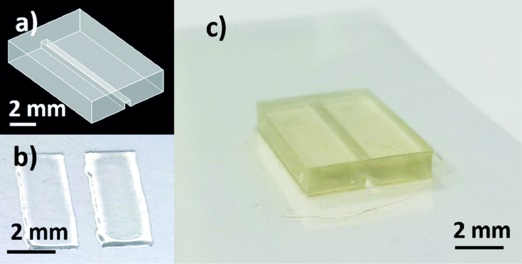
Fig. 1 a) CAD design used for 3D-printing of the microfluidic device. b) Homemade PVP-co-PMMA UV-curable ink, inkjet printed onto the flexible substrate to form a bonding area replicating the non-functional area of the microfluidic device. c) 3D-printed microfluidic structure bonded onto PQA1M flexible substrate using inkjet printed PVP-co-PMMA UV-curable ink.
As mentioned before, two different substrates (Optfine® PQA1M and Teonex® Q83) and two different UV-curable inks, namely PA-1210 and homemade PVP-co-PMMA ink, were used in order to find the best conditions for bonding of the 3D-printed devices to flexible substrates. The performance of the method was assessed quantitatively by measuring the bonding strength of the printed UV-curable ink layer. To obtain good ink wettability of the PQA1M substrate, which has an inherently low surface energy, oxygen plasma treatment was used. The desired test area corresponding to the dimensions of the test block was printed by using a resolution of 1693 dpi. In addition, the substrate holder in the inkjet printer was heated up to 40 °C, providing a uniform distribution of the deposited ink. The printed layer thickness was measured using a Dektak 3030 Surface Profiler, (Veeco Instruments Inc. USA) and was in the range of 3 microns for both inks.
First, the two inks were used to bond 3D-printed test bodies onto PQA1M substrates. The self-made gravitation based set-up (see Fig. S2†), was used for bonding strength measurements. Both inks delivered bonding forces, which were in the measurable range of the set-up. It was found that PA-1210 produced slightly higher bonding strength compared to the PVP-co-PMMA ink as shown in Fig. 2.
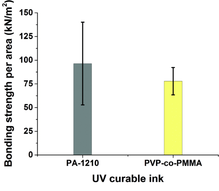
Fig. 2 Measured values of bonding strength per unit area required to break off the microfluidic device from the PQA1M substrate using two different inks: PA-1210 (n = 11) and PVP-co-PMMA (n = 12).
Next, another substrate (Teonex® Q83) was tested, in order to compare the behavior of both inks on both substrates. It was found that the PA-1210 cannot be used on this substrate, due to the surface energy/surface tension mismatch between the Q83 substrate and the ink. PA-1210 deposition led to irregularly distributed ink drops, whereas the PVP-co-PMMA ink on the same substrate produced a uniform distribution across the printed area. Nevertheless, the measured bonding strength differed between the PVP-co-PMMA samples, indicating that the bonding between the 3D-printed test bodies and the substrate was not always stable and reproducible.
Overall, bonding experiments on the Q83 substrate suffered from poor reproducibility resulting in a high standard deviation of the measured bonding strength. On the contrary, the values required to break the bonding on the PQA1M substrate were more reproducible and slightly greater than on Q83, yielding a smaller standard deviation as illustrated in Fig. 3. Since the bonding strength values obtained for the PVP-co-PMMA and PA-1210 inks did not vary greatly, in the following experiments we have proceeded with the less expensive PVP-co-PMMA ink and better performing PQA1M substrate. Moreover, having the option to alter PVP-co-PMMA ink's surface tension by adjusting the solvent mixture composition in house, enables the use of other microfluidic-compatible substrates. For example, for COC (cyclic olefin copolymer), having the surface energy of approximately 30 mN m−1, similar wetting behavior as for PQA1M is expected. On the contrary, for the polymers with higher surface energies, like PS (polystyrene, 40.7 mN m−1) and PMMA (polymethylmethacrylate, 41.1 mN m−1), much stronger wetting than on PQA1M is expected. In this case, to prevent excessive ink spreading, either milder or no surface treatment or ink surface tension increase would be required.
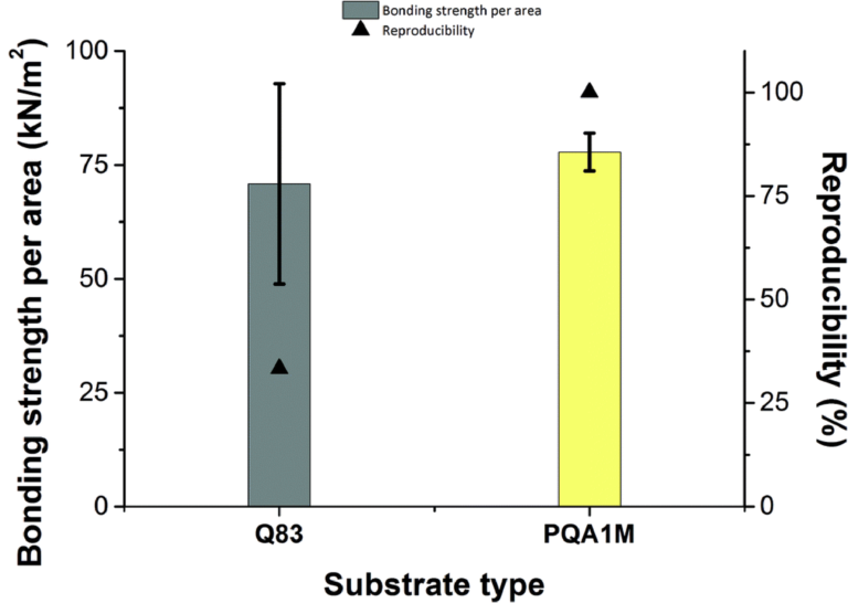
Fig. 3 Variation of the obtained forces in kN m−2 (left side) required to break the bonding between the microfluidic device and the two different types of substrates after curing of the PVP-co-PMMA ink. Reproducibility (%) of the bonding strength measurements (right side).
Bursting pressure experiments were performed using a homemade test device as described in the experimental section. It was found that the 3D-printed test block, sealed with a PQA1M foil using PVP-co-PMMA ink, can withstand a bursting pressure of up to 100 ± 9.8 kPa. This value is in the same range as other sealing methods reported in the literature13,32,33 and sufficient for sealing of the microfluidic structure for passive blood flow.
Proof-of-principle blood guiding experiments were carried out using the microfluidic devices bonded to PQA1M with the PVP-co-PMMA ink and heparinized rat blood. A syringe with blood was placed near the microfluidic opening and the blood was sucked in due to capillary forces only. Passive blood flow was achieved without any surface modification of the device and there was no leakage observed as shown in Fig. 4. Additionally, a long-term water exposure experiment was performed. Tap water was continuously pumped through the channel at 0.2 mL min−1 for 6 h for a total of 72 mL. Afterwards, heparinized blood was added to the channel and passively sucked in, revealing no leaks even after a long-term exposure to fluid. These results reveal good sealing of the microfluidic devices on flexible substrates using our bonding method.
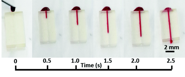
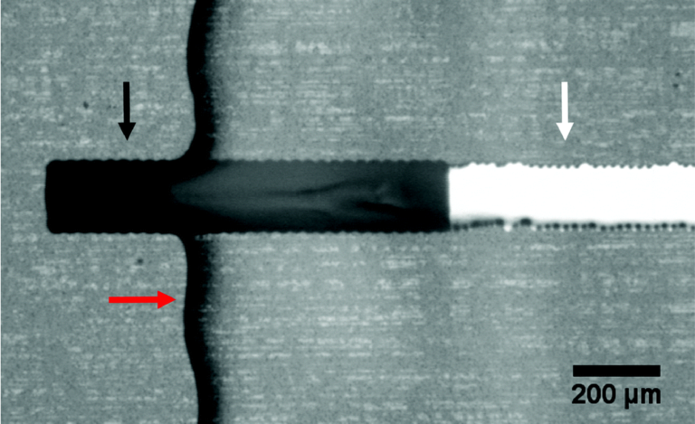
Fig. 4 Images of capillary flow of blood as a function of time inside the 3D-printed microfluidic device bonded onto a PQA1M flexible substrate with PVP-co-PMMA ink.
As mentioned before, good dielectric properties of the PVP-co-PMMA were demonstrated elsewhere.30,31 In order to test the insulating properties of our PVP-co-PMMA ink formulation in solution, we printed the ink as a passivation layer on top of silver and carbon tracks to form printed carbon microelectrodes. Silver, printed with a commercial silver nanoparticle ink, served as a feedline, while carbon, printed with a homemade carbon black formulation, was used as an electrode material. Fig. 5 shows a microscopic image of a printed microelectrode passivated using the same PVP-co-PMMA ink used for bonding experiments.