
Research Article Summary
5 Minute Read
University of British Columbia team streamlines organ-on-chip fabrication with 3D printed master molds
Title
PDMS Organ-On-Chip Design and Fabrication: Strategies for Improving Fluidic Integration and Chip Robustness of Rapidly Prototyped Microfluidic In Vitro Models
Authors
Tiffany C. Cameron, Avineet Randhawa, Samantha M. Grist, et al.
Journal
Micromachines (MDPI), 2022
DOI Link
Summary
Researchers at the University of British Columbia developed a set of fabrication strategies that use 3D-printed master molds to build PDMS organ-on-chip devices faster, while improving fluidic seal reliability and chip-to-chip consistency. The methods, from Cameron et al., were applied to a blood-brain barrier chip and a small-airway chip.
Summary Author
This page was prepared by CADworks3D to summarize and highlight a peer-reviewed research article authored by independent researchers utilizing the CADworks3D system.
Title
PDMS Organ-On-Chip Design and Fabrication: Strategies for Improving Fluidic Integration and Chip Robustness of Rapidly Prototyped Microfluidic In Vitro Models
Authors
Tiffany C. Cameron, Avineet Randhawa, Samantha M. Grist, et al.
Journal
Micromachines (MDPI), 2022
DOI Link
Key Results at a Glance
< 2 Hours
Master Mold Print Time
3D-printed molds were ready to cast PDMS in under two hours
< $5
CAD Resin Cost Per Mold
Cheap enough to iterate through several design revisions in a day
Over 85%
Fabrication Success Rate
Devices came out leak-free and usable across both chip designs
~4.5x Smoother
DLP vs. SLA Mold Surface
Lower roughness on DLP-printed molds meant clearer, easier-to-image PDMS
Objective
Organ-on-chip devices are small microfluidic platforms designed to mimic the structure and function of human tissue more closely than a standard well-plate culture. By combining tiny fluid channels with living cells, these chips can model physical conditions such as the shear stress from blood flow or the airflow across lung tissue, making them useful tools for drug screening and disease modeling.
Building an organ-on-chip typically starts with a master mold, a solid template used to shape microfluidic channels in a soft, flexible polymer called PDMS (polydimethylsiloxane). Traditionally, these molds are made using photolithography, a process that requires a clean room and specialized, expensive equipment. This requirement has kept organ-on-chip fabrication largely confined to a small number of well-resourced labs.
3D printing offers a faster, lower-cost path to making master molds, removing the need for clean room access. Rapid prototyping introduces its own challenges, though. Printed molds can have rougher surfaces than photolithography molds, and PDMS devices cast from them can develop leaks, especially at the fluidic ports where external tubing connects to the chip. These leaks become a bigger risk over long culture periods, when a device may need to run continuously for a week or more without disruption.
This paper addresses that gap directly. The researchers describe a set of design and fabrication strategies meant to make 3D-printed master molds more practical for routine organ-on-chip work, with a focus on improving PDMS layer thickness, strengthening fluidic connections, and reducing leakage. These strategies were applied to two different chip designs, a blood-brain barrier model and a small-airway model, to test how well the approach held up across different device geometries and culture conditions.
Methodology and Design
Each chip began as a digital CAD model, designed in SOLIDWORKS and exported into a format the 3D printer’s software could read. Master molds were printed using either a DLP (digital light processing) printer or an SLA (stereolithography) printer. Liquid PDMS was then poured into the mold, degassed, cured in an oven, peeled away, and bonded into a two-layer microfluidic chip separated by a thin, porous membrane that supports the cultured cells.
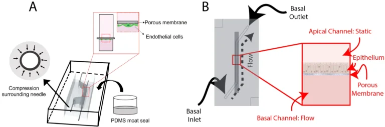
Figure 1. (A) Schematic of the blood-brain barrier chip, which uses side-loaded fluidic ports and a PDMS moat seal, with endothelial cells seeded on the underside of the membrane. (B) Schematic of the airway chip, which uses top-loaded ports, with epithelial cells seeded on top of the membrane. Both designs sandwich a porous membrane between two PDMS layers. Source: Cameron, Randhawa et al. PDMS Organ-On-Chip Design and Fabrication. Micromachines. 2022.
These fabrication methods were applied to two different organ-on-chip designs, each modeling a distinct part of the body.
Blood-Brain Barrier Chip
Small-Airway Chip
The blood-brain barrier chip used side-loaded fluidic ports, positioned along the side of the device rather than the top. This allows the whole chip to be flipped for imaging from either side, useful when culturing more than one cell type across the membrane. To form these ports, thin needles were inserted directly into the mold before pouring PDMS, sacrificially shaping the port geometry around them and creating a snug fit once the needles were swapped for the final fluidic connectors. Endothelial cells, the type that line blood vessels, were seeded onto the membrane and connected to a slow, continuous flow of culture media using a syringe pump.
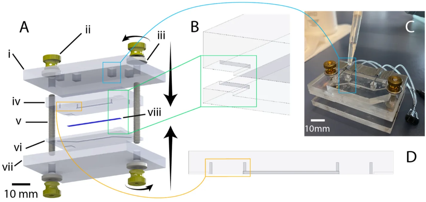
Figure 2. (A) Assembled chips placed into a flat dish. (B) Liquid PDMS poured around the chips. (C) An acrylic sheet placed on top to keep the central channel area clear. (D) A weight used to hold the chips in place while the PDMS cures. (E) The finished PDMS block, with chips embedded and ready to connect to fluidics. Source: Cameron, Randhawa et al. PDMS Organ-On-Chip Design and Fabrication. Micromachines. 2022.
The small-airway chip used top-loaded ports instead, formed by combining raised features in the mold with a biopsy punch after the PDMS had cured. Because this chip only required imaging from one side, side-loading wasn’t necessary, and top-loading made punching more straightforward. Airway epithelial cells were seeded onto the membrane and cultured under a peristaltic pump-driven, recirculating flow, chosen to approximate the shear stress that lung tissue experiences from airflow in the body. Both chip designs used a PDMS layer thickness of 6 mm, giving the metal needles used for fluidic connections enough surrounding material to stay firmly seated during handling.
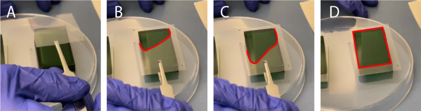
Figure 3. (A) Exploded CAD view of the airway chip and its acrylic compression clamp. (B) Corner alignment features that guide the two PDMS layers into position during bonding. (C) Liquid PDMS dispensed into the clamp to reinforce the seal around each fluidic port. (D) Punch guides marking where each port is biopsy-punched. Source: Cameron, Randhawa et al. PDMS Organ-On-Chip Design and Fabrication. Micromachines. 2022.
On the fabrication side, the DLP printer offered an x-y resolution of 30 µm with a user-selectable z-resolution, set to 30 µm for these molds, compared to 140 µm x-y and 25 µm z-resolution on the SLA printer. Before curing, a transparency film was gently laid over each PDMS-filled mold and weighed down, a simple step that helped flatten the top surface and reduce thickness variation across the finished device. Bonding the two PDMS layers together differed by chip type: the blood-brain barrier chip used oxygen plasma treatment, while the small-airway chip used a partial-cure bonding method that avoids the need for a plasma cleaner. To reinforce the fluidic connections after bonding, the blood-brain barrier chip was encased in a PDMS mold “moat” poured around the tubing, while the small-airway chip used a laser-cut acrylic clamp paired with small amounts of liquid PDMS dispensed around each port.
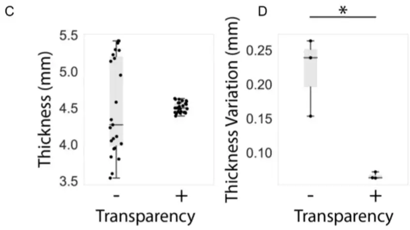
Figure 4. (A–D) Sequence showing a transparency film being gradually lowered over PDMS poured into a 3D printed mold, starting from one corner. Lowering the film slowly like this helps prevent air bubbles from forming between the film and the PDMS. Source: Cameron, Randhawa et al. PDMS Organ-On-Chip Design and Fabrication. Micromachines. 2022.
Results
Across both chip designs, the fabrication process achieved a success rate of over 85%, meaning the large majority of devices came out leak-free and usable after bonding.
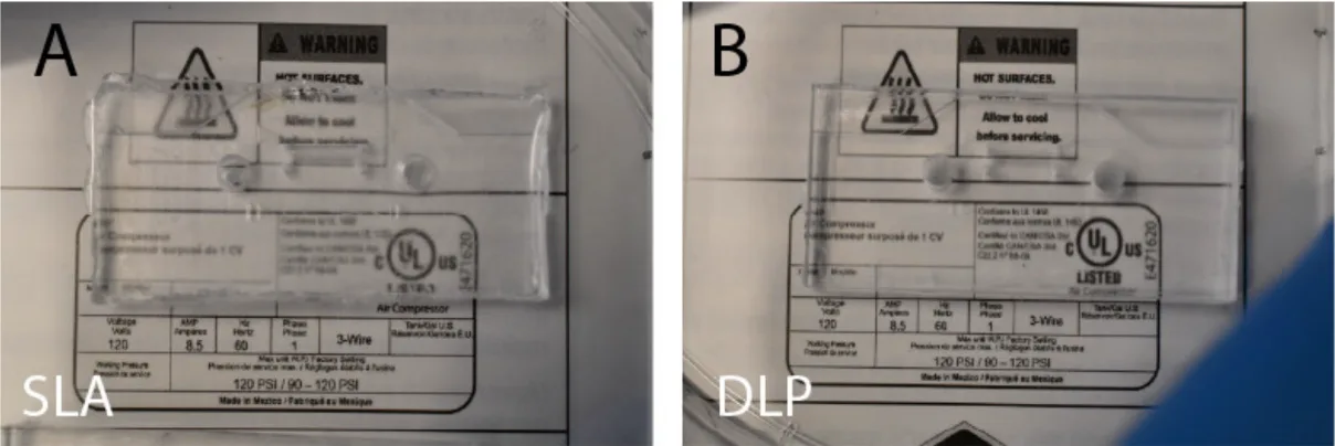
A central part of that reliability traces back to the master molds themselves. Molds printed on the DLP printer had a noticeably smoother surface than those printed on the SLA printer, with average surface roughness roughly 4.5 times lower. This mattered downstream: PDMS devices cast from the DLP-printed molds were more optically clear, making them easier to image under a microscope, a practical advantage for labs running live-cell imaging.
The molds were also fast and inexpensive to produce. Each master mold took under two hours to print and cost less than $5 CAD in resin, making it practical to iterate on a design several times in a single day rather than waiting on outside fabrication.
Small changes to the casting process also made a measurable difference. Adding a transparency film step while curing the PDMS significantly reduced variation in PDMS thickness across a device, which matters because uneven thickness can cause channels to deform unevenly when a chip is compressed to help form a fluidic seal. The reinforced fluidic connections held up well over time, too. Chips sealed with a PDMS mold “moat” resisted degradation after 24 hours of ethanol exposure, while chips sealed with epoxy showed visible delamination under the same test, a meaningful finding for any application involving frequent disinfection or extended culture periods.

Figure 5. (C) PDMS thickness measured at several points across replicate devices, with and without a transparency film. (D) Thickness variability within each individual device. Devices cast with the transparency film were consistently more uniform on both measures. Source: Cameron, Randhawa et al. PDMS Organ-On-Chip Design and Fabrication. Micromachines. 2022.
“3D printers and laser cutters are becoming more common in research laboratories.”
— Cameron et al., Micromachines (2022)
Products Used In This Study

Questions on how our 3D printing system can work for your research? Connect with one of our specialists.
More Research Article Summaries
McGill University researchers build a 3D printed double-sided mold system to shape and merge brain organoids on a chip
University of Hawaiʻi researchers 3D print wearable "sweatainer" devices with true microscale internal channels
Want to read more article summaries?
We summarize the latest microfluidics and 3D printing research.
Curated from peer-reviewed publications featuring the CADworks3D system.