
Research Article Summary
5 Minute Read
Koç University researchers automate microfluidic chip design and 3D print the working circuits
Title
ML-automated microfluidic circuit design
Authors
Mehmet Tugrul Birtek, Vural Aktas, Bora Aktas, et al.
Journal
Science Advances, Vol. 12, Issue 5 (2026)
DOI Link
Summary
Researchers built an open-access design tool that turns a simple drag-and-drop layout into a 3D printable microfluidic chip, letting non-experts generate working fluidic circuits without the usual trial-and-error or specialist software. Validated by printing and testing real chips, the designs reproduced their target flow distributions with roughly 90% accuracy (Birtek et al.).

Summary Author
This page was prepared by CADworks3D to summarize and highlight a peer-reviewed research article authored by independent researchers utilizing the CADworks3D system.
Title
ML-automated microfluidic circuit design
Authors
Mehmet Tugrul Birtek, Vural Aktas, Bora Aktas, et al.
Journal
Science Advances, Vol. 12, Issue 5 (2026)
DOI Link
Key Results at a Glance
~90%
Flow accuracy
Printed chips matched their target flow splits closely.
40 µm
Printed feature limit
Smallest channel width the printer could reliably resolve.
< 60 s
Design time
A finished, print-ready file generated on a normal laptop.
3 chips
Validated by printing
Two-, three-, and four-outlet circuits all fabricated and tested.
Objective
Microfluidic chips move tiny volumes of fluid through networks of channels, many of them just tens of µm wide. They sit underneath a lot of modern biomedical work: organ-on-chip models that recreate how fluid moves through tissue, point-of-care diagnostics that run tests on a single drop, and tools that sort cells or mix reagents in precise ratios. In all of these, the geometry of the channels does the real work. It decides how fast fluid moves, where it splits, and how much ends up in each branch.
The problem is that getting that geometry right is hard. To make fluid divide into exactly the proportions you want, at the flow rates you want, a designer normally guesses at a layout, simulates it, adjusts it, and repeats. That loop demands specialist CAD skills and a working knowledge of fluid mechanics, and it often still ends with trial-and-error at the bench. This keeps precise microfluidic design in the hands of a small group of experts.
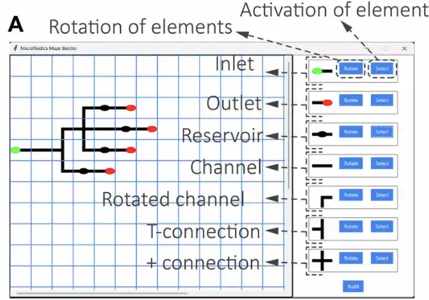
Figure 1. The design tool's interface. A user lays out reservoirs and channels and sets target flow rates, and the software returns a 3D printable file of the finished chip. Source: Birtek et al. ML-automated microfluidic circuit design. Science Advances. 2026.
The standard computational tools do not fully solve this. Computational fluid dynamics and finite element analysis can predict how a design will behave, but they are slow, resource-heavy, and difficult to set up correctly. They tell you whether a design works after you have already designed it; they do not give you a working design to start with. That leaves a gap: there has been no fast, accessible route for a non-expert to go from a description of the flow they want to a chip they can manufacture.
This paper sets out to close that gap with a tool that handles the hard part of the design, predicts behaviour instantly instead of through lengthy simulation, and exports a file ready to 3D print.
Methodology and Design
The study’s fabrication pipeline starts with the design software itself. Reservoirs and channels are placed on a grid, a flow rate is assigned to each outlet, and the layout is converted into a circuit whose required channel resistances are calculated and packed into compact, maze-like paths rather than long, straight channels. A machine learning model, trained on a large library of simulated maze geometries, estimates each channel’s resistance almost instantly, letting a search routine reshape the maze until it hits the target, typically finishing in under a minute on an ordinary laptop. The finished design exports as a standard .stl file, printable directly as a chip or used as a mold for soft lithography, the mold route the team used in this study.
That pipeline was used to generate circuits covering a range of flow-distribution needs, along with a chip built specifically for soft lithography:
Two-Outlet Circuit
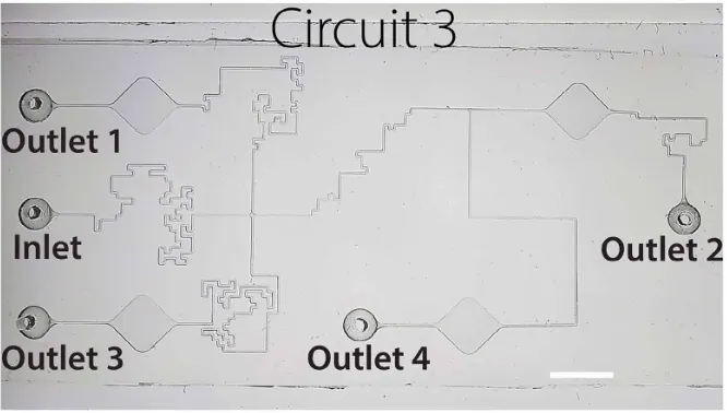
Three-Outlet Circuit
Four-Outlet Circuit
Mold-Based Chip

Figure 2. The maze concept. Each channel is built inside a 10 mm grid from 0.5 mm steps, packing a long, precise flow path into a small footprint. Dimensions are in µm. Source: Birtek et al. ML-automated microfluidic circuit design. Science Advances. 2026.
The logic behind these circuits comes from an analogy with electronics: the shape of a microfluidic channel sets its fluidic resistance much like the shape of a wire sets electrical resistance, and resistance together with pressure decides how flow divides between branches. The two-outlet circuit puts this to work for flow splitting, the three-outlet circuit extends it to partitioning flow across three branches, and the four-outlet circuit distributes flow in parallel across four outlets. Packing each channel’s resistance into a maze-like path instead of a long, straight run is what lets these designs reach a wide range of resistance values without enlarging the chip or adding external tubing.
The mold-based chip puts the tool’s soft lithography output style to use. Instead of printing a standalone chip directly, the design is exported as a mold, printed on a CADworks3D digital light processing resin printer, and then used to cast PDMS, a clear silicone, into the finished channel geometry.
Across all four designs, the process stays fabrication-aware, which is what keeps the outputs printable rather than just theoretical. Channel widths and heights are kept above the printer’s resolution limit, sharp corners are minimized since they tend to cause print defects, and the tool deliberately aims slightly below the target resistance, since printing imperfections usually push real resistance upward.
Results
The printed chips performed close to their digital targets. Across the two, three, and four-outlet circuits, measured flow distributions matched the intended splits with roughly 90% accuracy, climbing to about 95% for the four-outlet design. As an independent check, simulations of the same printed chips agreed with the bench measurements to within about 92%, confirming that the designs themselves were sound.
The design step was also fast and accessible. A complete, print-ready file was produced in under 60 seconds on a standard consumer laptop, with no manual tuning. The printer’s reliable feature size set a 40 µm floor on channel dimensions, and the workflow was validated by physically printing and flow-testing three different chips rather than relying on simulation alone.
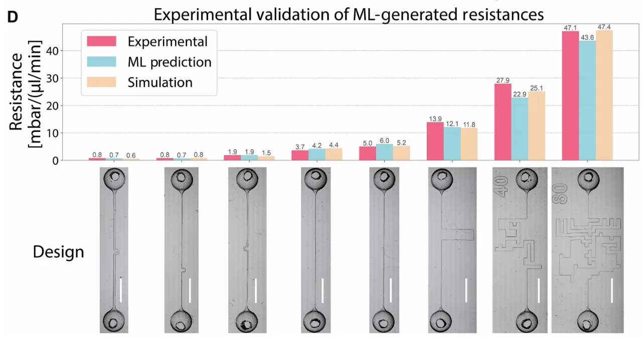
Figure 3. Eight printed channels designed for set resistances. Printed dimensions vary slightly from the digital design, but the underlying model still predicts their behaviour accurately. Scale bars, 5 mm. Source: Birtek et al. ML-automated microfluidic circuit design. Science Advances. 2026.
The work also reports a clear limitation. In the lowest-flow channel of the two-outlet chip, flow occasionally stalled when it dropped below about 1.4 µl/min, an effect linked to the surface roughness of the printed channels. A small increase in inlet pressure restored steady flow, and smoother printed surfaces are expected to remove the effect entirely.
“By streamlining and automating microfluidic circuit creation, μFG not only lowers the barrier to entry for nonexperts but also showcases a principled and efficient application of ML to fluidic system design.”
— Birtek et al., Science Advances (2026)
Products Used In This Study

Questions on how our 3D printing system can work for your research? Connect with one of our specialists.
More Research Article Summaries
McGill University researchers build a 3D printed double-sided mold system to shape and merge brain organoids on a chip
University of Hawaiʻi researchers 3D print wearable "sweatainer" devices with true microscale internal channels
Want to read more article summaries?
We summarize the latest microfluidics and 3D printing research.
Curated from peer-reviewed publications featuring the CADworks3D system.