Selective fluorination of the surface of polymeric materials after stereolithography 3D printing
Megan A. Catterton, Alyssa N. Montalbine, and Rebecca R. Pompano
With the microfluidics community embracing 3D resin printing as a rapid fabrication method, controlling surface chemistry has emerged as a new challenge. Fluorination of 3D printed surfaces is highly desirable in many applications due to chemical inertness, low friction coefficients, anti-fouling properties and the potential for selective hydrophobic patterning. Despite sporadic reports, silanization methods have not been optimized for covalent bonding with polymeric resins. As a case study, we tested the silanization of a commercially available (meth)acrylate-based resin (BV-007A) with a fluoroalkyl trichlorosilane. Interestingly, plasma oxidation was unnecessary for silanization of this resin, and indeed was ineffective. Solvent-based deposition in a fluorinated oil (FC-40) generated significantly higher contact angles than deposition in ethanol or gas-phase deposition, yielding hydrophobic surfaces with contact angle > 110° under optimized conditions. Attenuated Total Reflectance-Fourier Transform Infrared (ATR-FTIR) spectroscopy indicated that the increase in contact angle correlated with consumption of a carbonyl moiety, suggesting covalent bonding of the silane without plasma oxidation. Consistent with a covalent bond, the silanization was resistant to mechanical damage and hydrolysis in methanol, and was stable over long-term storage. When tested on a suite of photocrosslinkable resins, this silanization protocol generated highly hydrophobic surfaces (contact angle > 110°) on three resins and moderate hydrophobicity (90 – 100°) on the remainder. Selective patterning of hydrophobic regions in an open 3D-printed microchannel was possible in combination with simple masking techniques. Thus, this facile fluorination strategy is expected to be applicable for resin-printed materials in a variety of contexts including micropatterning and multiphase microfluidics.
Keywords: Two-phase microfluidics, Droplet microfluidics, low surface energy, Digital Light processing (DLP), stereolithography printing (SLA)
We kindly thank the researchers at University of Virginia for this collaboration, and for sharing the results obtained with their system.

Introduction
The microfluidics community has increasingly adopted 3D printing for device fabrication, including with fused deposition modeling1–3 and with resin-based methods such as stereolithography (SLA) and digital light processing (DLP) printing.4,5 As a result, methods to control the surface chemistry of 3D printed devices are emerging as a critical challenge, especially for microscale features produced by resin printing.6 In resin printing, UV/visible light is used to cross-link a photocurable, polymeric resin in a layer-by-layer fashion to produce a 3D structure.4,5 While methods for surface functionalization are well established for traditional materials such as glass and polydimethylsiloxane (PDMS), those methods do not necessarily translate directly to the polymeric materials used for 3D printing. A particular challenge is to generate a fluorinated surface on a 3D printed chip. Fluorinated surfaces offer many advantages for microfluidic device design, such as controlled surface wettability for passive fluidic control, chemical inertness, resistance to surface fouling, and low friction coefficient.7–10 These properties historically made fluorinated surfaces invaluable for multiphase microfluidic chips.11–16 By patterning fluorination amidst a non-fluorinated surface, patterned hydrophobicity has been used to generate droplets, create microarrays, and control microfluidic valving.17–19 Therefore, facile methods to selectively fluorinate the surface of polymeric SLA and DLP resins are required, particularly for the commercially available resins used by most laboratories.
Currently, there are few methods available to generate a fluorinated surface on 3D printed material, particularly a patterned surface. One option is to start directly with a fluorinated resin,20 but these are rare in practice due to limited commercial options. Additionally, fully fluorinated devices are not readily patterned at the surface due to their chemical inertness. Alternatively, selective surface patterning is possible by using printed pieces modified at the surface with fluorinated coatings.6,21,22 Polymeric liquid coatings provide a robust hydrophobic layer up to hundreds of micrometers thick,21 but may be inappropriate for microscale features that are easily blocked or filled in. A chemical vapor deposition method can be used to generate a thin, highly hydrophobic coating by polymerizing a fluorinated acrylate film on the surface, but has limited use in enclosed channels.23,24 Thin coatings can also be achieved by including a polymerization initiator in the resin, to provide covalent anchor points for fluorinated polymer brushes.22 However, polymer brushes may exhibit poor mechanical stability during abrasion.6
Silanization using fluorinated silanes is a reliable method for molecular-scale surface modification of glass and polydimethylsiloxane (PDMS),25,26 but silanization of polymeric materials can be challenging. Historically, polymers have been chemically modified primarily by strategies such as wet etching, plasma or corona treatment, or coatings, rather than direct silanization.27–31 Extensive surface oxidation is usually required to generate enough silane-reactive functional groups (e.g. hydroxyls) at the polymer surface, but not all polymers can withstand such treatment, as they may degrade after plasma exposure.7,27,28,32,33 So far there have been sporadic reports of silanization of resin 3D printed microfluidic devices, e.g. to fluorinate 3D printed molds for PDMS34 and to attach reactive functionalities for bonding of 3D printed pieces.35 In some cases, the printed polymer had to be coated with a layer of silica to enable silanization.36,37 To date, there has been little testing of the conditions required for direct fluoroalkyl silanization of resin printed pieces, nor characterization of the hydrophobicity and stability of the silanized surface.
Here, we aimed to develop a robust and straightforward silanization protocol using (tridecafluoro-1,1,2,2-tetrahydrooctyl) trichlorosilane, a fluoroalkyl silane, and a suite of commercially available SLA and DLP resins to generate a highly fluorinated surface for use in microfluidic devices. While optimizing the reaction conditions to generate the highest possible contact angle, we found, surprisingly, that surface oxidation using air plasma was unnecessary for silanization. To characterize the surface and investigate reactive groups involved in forming a covalent bond between the printed resin and the fluoroalkyl silane, we measured the air/water contact angle of the silanized surface and used infrared (IR) spectroscopy. We tested the ability of the method to selectively pattern hydrophobic regions in a 3D printed open microchannel, and further tested the applicability of the optimized method to four additional resins. The method is facile, versatile, and allows for dynamic patterning of a hydrophobic surface on a resin-printed piece.
Experimental Section
3D Printing
Printed parts were designed using Autodesk Inventor 2018. The CAD files were sliced at 50 μM intervals using MII Utility Shortcut V 3.27 and printed using a CADworks3D M50–405 printer (MiiCraft, CADworks3D). The commercial resins included were BV-007A (Clear) (MiiCraft, CADworks 3D), Green Master Mold (MiiCraft, CADworks 3D), Dental LT Clear Resin (V2) (FormLabs), and Asiga PlasClear V2 (iMakr). A house-made photoresin consisting of 0.4 % w/v phenylbis(2,4,6-trimethylbenzoyl)phosphineoxide (Irgacure 819) (Therofisher) dissolved in poly(ethylene glycol) diacrylate (PEG-DA) (MW 250) (Sigma Aldrich) was also included in the suite of resins tested.38 The printer setting for each resin can be found in Table S1. Printed parts were rinsed with either 95% ethanol (Koptec), isopropanol (Fisher chemical), or methanol (Fisher chemical) as recommended for by the manufacturer for the resin. Printed pieces were post-cured in an UV-light box, then stored at room temperature on the bench top in polystyrene petri dishes (Fisher) prior to silanization.
Surface Treatment of 3D Printed Pieces
Where noted, some printed parts were plasma treated using a BD-20AC laboratory corona treater (Electro-Technic Products, Chicago IL, USA). Printed parts were placed 3 mm below the plasma source and treated for 5 – 60 s immediately prior to surface silanization. For gas-phase deposition, 200 μL of neat tridecafluoro-1,1,2,2-tetrahydrooctyl trichlorosilane (Gelest Inc., Morrisville PA, USA) was placed in a vacuum desiccator in a small polypropylene dish, followed immediately by the printed parts, and a vacuum was applied for 2 hours at room temperature. For solvent deposition, the surface of the printed part was submerged in a 10% v/v solution of tridecafluoro-1,1,2,2-tetrahydrooctyl trichlorosilane in solvent (Fluorinert FC-40 (Sigma Aldrich) or 200 proof ethanol (Koptec) for 30 min at room temperature, unless otherwise specified. After silanization, surfaces were rinsed with 95% ethanol and DI water and dried with a nitrogen gun.
Contact Angle Measurement
Surface air/water contact angles were measured using a ramé-hart goniometer (model 200–00, ramé-hart instrument co., Succasunna NJ, USA) and DROPimage Advanced software. Contact angle was measured for 3 separate printed pieces per condition, by pipetting one 5-μL droplet of DI water per print onto the silanized surface. 8×8×8 mm3 cubes were used for the printed piece, and oriented so the smooth flat face of the printed cube was tested.
Surface Chemistry Characterization with Infrared Spectroscopy
The surface chemistry of the printed parts was examined by using an iD7 ATR Nicolet IS5 FT-IR spectrophotometer (Thermo Fischer Scientific). The IR spectrum was measured on the flat smooth face of a 10×10×2 mm3 printed rectangular prism. The instrument was set to a constant gain of 4, and the background was collected prior to each session. Data was collected, visualized, and processed using the OMNIC software (Thermo Fischer Scientific).
Robustness testing
Printed pieces were silanized according to the optimized method. To test the resistance to mechanical damage, the parts were clamped with two binder clips against a clean petri dish to apply constant pressure and rubbed together for 30 s at a time. Air/water contact angles of the silanized surfaces were measured before and after the mechanical test. To test stability after storage, silanized printed parts were stored in a petri dish at room temperature under ambient light, and the air/water contact angles were repeatedly measured over time. Finally, contact angles were measured before and after soaking the printed parts for 2 hours in methanol.
Selective Patterning of 3D Printed Surfaces
Rectangular prisms (20×15×3 mm3) were printed using BV-007A resin. Each print contained an embossed cross-shaped open channel with a rectangular cross-section (1 mm deep, 2 mm wide). Scotch tape (3M) was cut and aligned manually to prevent the fluoroalkyl silane solution from coming into contact with portions of the printed surface inside the channel. Taped pieces were immersed in a solution of 10% v/v (tridecafluoro-1,1,2,2-tetrahydrooctyl) trichlorosilane in FC-40 for 30 min in a fume hood at room temperature. After treatment, pieces were rinsed with 95% ethanol and DI water and dried with nitrogen. To test the functionality of the patterned surface, solutions of food coloring in water were pipetted into the arms of the embossed features.
3D printed Droplet Generator
A simple T-junction was designed in AutoCAD, consisting of a 10 mm channel with a 0.5 × 0.5 mm cross-section, with a 3 mm channel length with a 0.5 × 0.5 mm cross-section channel that intersects the longer channel. The enclosed channel was fluorinated by filling the channel with a solution of 10% v/v (tridecafluoro-1,1,2,2-tetrahydrooctyl) trichlorosilane in FC-40 for 30 min, in a fume hood at room temperature. A syringe (1 mL, BD) with a 27 G needle (BD) was filled with FC-40 oil containing 0.5 mg/mL RfOEG (triethyleneglycol mono[1H,1H-perfluorooctyl]ether, a surfactant synthesized in house).29 Another syringe was filled with 1 M Fe(SCN)2+(aq) in water. Connections to the device were made with nonshrinkable PTFE TT-30 tubing (Weico Wire, Edgewood NY, USA). Pressure driven flow was achieved using a Chemyx syringe pump (Fusion 200, Houston TX, USA), using flow rates of 30 μL/min for the oil and 10 μL/min for the aqueous solution. Brightfield images were collected using an Zeiss AxioZoom macroscope (Carl Zeiss Microscopy, Germany) at 1.6 magnification with an Axiocam 506 Mono camera. Images were collected at 1 s intervals for 10 s. All images were analyzed in Zen 2 software.
Data Analysis
Statistical tests and curve fitting were performed using Graphpad Prism version 9. Half-lives and half-times of exponential fits were calculated according to half time = ln 2/k, where k is the rate constant from the fit.
Results and Discussion
Plasma oxidation was not necessary or effective for silanization of SLA printed pieces
While the precise composition of most commercial resins is proprietary, MSDS information states that many are based on acrylate and/or methacrylate polymers (Figure 1a). Silanization of related polymeric materials such as poly(methyl methacrylate) (PMMA) requires oxidation to generate hydroxyl groups that undergo condensation reactions with the silane reagent.7,14 Similarly, prior reports of silanization of an acrylate-based 3D printed material included activation of the surface with plasma treatment.34,35 Therefore, we first tested the efficacy of silanization of 3D printed pieces as a function of the duration of exposure to air plasma. As a case study, we selected a clear (meth)acrylate-based resin formulated specifically for printing microfluidic devices, BV-007A resin from MiiCraft, and sought to silanize it with (tridecafluoro-1,1,2,2-tetrahydrooctyl) trichlorosilane (Figure 1a). Two common methods of silanization were tested: gas-phase deposition29,34,39–41 and liquid-phase deposition.14,29 For the latter, we used a 10% v/v solution of silane in FC-40 fluorinated oil.t.
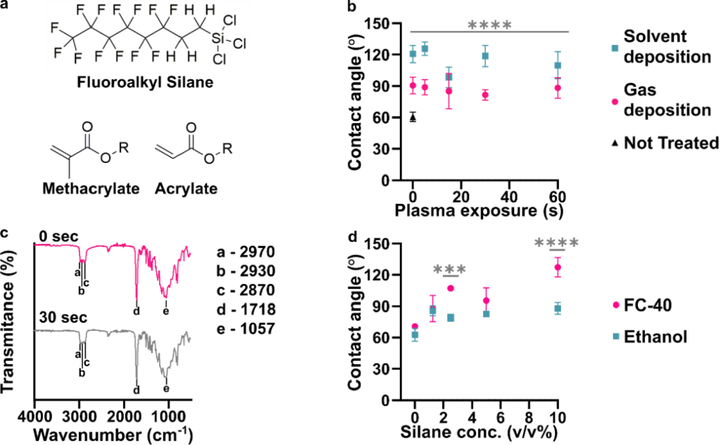
Figure 1: Effects of plasma treatment and silanization on the chemistry and hydrophobicity of DLP printed pieces. (a) Chemical structures of the fluoroalkyl silane and monomer acylate and methacrylate base used for many resin formulations. (b) Air/water contact angles of BV-007A after silanization by solution-phase (blue squares, FC-40 solvent) or gas-phase (pink dots) deposition after varied times of treatment with air plasma (n=3, mean ± std dev). The black triangle represents printed BV-007A pieces that received neither plasma treatment nor any silane treatment. Two-way ANOVA for solution vs gas-phase silanization (**** p<0.0001). (c) ATR-FT IR spectrum of the BV-007A surface with no exposure to air plasma (pink) and after 30 s plasma treatment (grey), without silanization. Spectra are offset to display spectral features. (d) Air/water contact angles of BV-007A surface after solution-phase silanization in FC-40 (pink dot) or ethanol (blue square). Two-way ANOVA with Sidak’s multiple comparisons to compare between solvents (****p <0.0001, *** p<0.001).
Surprisingly, we found that even in the absence of plasma treatment (0 s exposure), silanization significantly increased the air/water contact angle for both methods (gas phase, p<0.005; solvent, p<0.001) compared to the 60° contact angle of the unslianized printed piece angle (Figure 1b, Figure S1). While gas-phase deposition provided a contact angle near 90°, the lower boundary for hydrophobicity, the solution-phase method provided a significantly larger (p < 0.0001) contact angle close to 120°, the upper limit for a flat, fluorinated surface.26,42,43 Plasma treatment from 5 to 60 s did not further increase the contact angle. Wanting to further test the impact of plasma cleaning on the surface chemistry, we next used IR spectroscopy to investigate functional groups on the surface of printed BV-007A pieces.
We expected that sufficient exposure of BV-007A pieces to air plasma would oxidize the surface to form alcohol and/or carboxylic acid groups.44 To characterize the surface chemistry and investigate the extent of surface activation at short plasma treatment times, we collected surface ATR FI-IR spectra of the printed pieces (Figure 1c). As expected for (meth)acrylate-based BV-007A, the spectra closely resembled that of a commercial sheet of PMMA (Figure S2). The peaks at 2970, 2930, and 2870 cm−1 were assigned to alkane sp3 C-H stretching. A major C=O stretch peak at 1718 cm−1 was attributed to the carbonyl in the backbone of the (meth)acrylate-based polymer as well as other carbonyl-containing components of the resin, e.g. photoinitiators and photoabsorbers. The C-O-C stretching was assigned to the peaks ranging from 1000 – 1300 cm−1 in the fingerprint region.45 Treating BV-007A printed pieces with air plasma for 30 – 60 s did not alter the IR spectra substantially (Figure 1c and data not shown). In particular, no characteristically broad alcohol band (3550 – 3200 cm−1) was observed, and there was no change in the alkyl CH stretches or carbonyl peak. These data were consistent with plasma treatment neither affecting the contact angle of the material (Table S2) nor improving its silanization (Figure 1b). As a positive control, oxidation from the plasma treatment was verified using both glass and PDMS, whose contact angle decreased after 5 s of plasma treatment as expected (Table S2). Prior reports of plasma treatment of PMMA used longer treatment times (5 min and greater) to modulate the surface polarity,46,47 but we found that treatment of BV-007A pieces with air plasma for longer than 2 min generated cracks in the surface. Since plasma treatment was unnecessary for silanization and in fact was ineffective at oxidizing the BV-007A surface at short times, we proceeded to optimize and characterize the silanization of BV-007A pieces it its absence.
Solvent deposition was most effective when a fluorocarbon oil was used as a solvent.
Having established that solution-phase deposition was more effective than gas-phase deposition, we further optimized the choice of solvent and concentration of silane. Two solvents were tested: ethanol (200 proof), a common solvent for deposition of trichlorosilanes,29,30 and FC-40, a fluorinated oil.14 Whereas deposition from ethanol solution was largely ineffective (contact angles < 90°) regardless of silane concentration, deposition from FC-40 solution had a concentration-dependent effect, yielding an average contact angle of ~ 120° at 10 % v/v silane (Figure 1d). Exposure to FC-40 alone, without silane, did not increase the contact angle significantly (Figure S1). Therefore, 10% v/v of the fluorinated silane in FC-40 was used for all further experiments.
Time dependence of the reaction provides support for covalent bond formation
Next, we tested the time dependence of the silanization reaction. The contact angle increased in a time-dependent manner with a half-time of 3.4 min, reaching a plateau after 15 min that was unchanged for the rest of the testing period, up to 60 min (Figure 2a). To complement the contact angle data and assess the extent of bond formation between the fluoroalkyl silane and BV-007A, ATR-FT IR spectra were collected from these samples (Figure 2b). The spectra changed noticeably over this time period. In particular, the carbonyl stretch at 1716 cm−1 decreased in intensity over time (Figure 2b – c), and the peak area was well fit by exponential decay equation with a half-life of 3.5 min (Figure 2d). This observation suggested a molecular reaction between the resin and the fluoroalkyl silane that consumes a carbonyl. The data do not distinguish between the methacrylate carbonyl and any carbonyls that may be present in the resin’s photoinitiators or photoabsorbers, but these additives typically are a minor constituent of the resin. An immediate increase in fingerprint region intensity was consistent with the addition of fluoroalkyl silane to the surface of the print (Figure 2b, ,cc and ande).e). New peaks included those at 1023 cm−1, assigned to Si-O-R stretching,48 1232 and 1142 cm−1, consistent with asymmetric and symmetric C-F stretches, and 707 cm−1, assigned to the C-F wag.49 This increase had a half-time of only 2.0 min, shorter than the decay of the carbonyl, suggesting that physical adsorption of the silane may have preceded the covalent reaction (Figure S3). The -C-H stretch peaks at 2872, 2932, and 2971 cm−1 were still present after silanization (Figure 2b – c).50
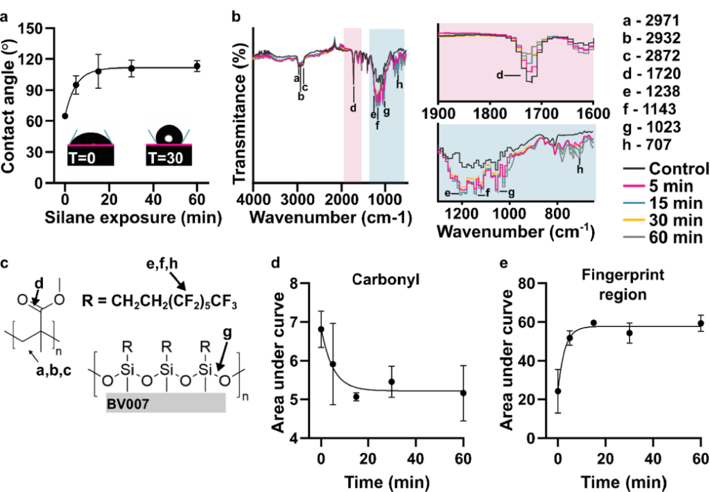
Figure 2: Time dependence of the chemical reaction. (a) Contact angle of the fluorinated surface after various amount of silane treatment (n=3, mean ± std dev). The data were fit to an exponential curve, y = 111 – 46.9e−0.201x, R2 =0.844. Insets show images of droplets on BV-007A surface after 0 and 30 min of silanization. (b) ATR-FT IR spectrum of printed BV-007A pieces after various times of silane treatment. Two regions of interest are highlighted: the carbonyl peak at 1720 cm−1 and the finger print regions 650–1300 cm−1. (c) The chemical structures present in a methyl methacrylate-based resin and from the fluoroalkyl are labeled with the corresponding IR spectra peak. (d) The area under the carbonyl peak decreased in a time-dependent manner (n=3, mean ± std dev), fit to an exponential decay y = 55.9e−0.115x +43.3, R2 = 0.936. (e) The area under the curve of the finger print region increased in a time-dependent manner, fit to an exponential curve, y = 57.7 – 24.2e−0.348x, R2 =0.855.
From both the contact angle measurements and the IR spectra, we concluded that the silanization reaction likely resulted in a covalent bond, and that 30 min was sufficient for reaction completion and generation of a highly hydrophobic surface. We note that the mechanism for such a reaction does not match that of typical silanizations, which occur through a condensation reaction with hydroxyl groups on the surface of the material. In this case, there were no detectable hydroxyl groups, yet surface modification still occurred. We were unable to find a precedent for the reaction of a tri-substituted silane with (meth)acrylate; the closest reaction we found in literature was that of silyl radicals attacking alkenes and acrylates,51 but we would not expect formation of a silyl radical in this system.
Robustness and stability of fluorination procedure
To establish the practical utility of the method, we considered the sensitivity of the procedure to the state of the printed piece and characterized the stability of the hydrophobic surface. First, we considered that the surface chemistry of the printed piece may change over time and potentially alter the reactivity with the trichlorosilane, e.g. due to slow cross-linking of residual monomer under ambient light.52,53 To test the efficacy of silanization as a function of light-induced aging, printed parts were treated with either the manufacturer-recommended 20 s or an extended 360-s UV exposure during the post-curing process. We estimate that continuous 360-s exposure was an equivalent dose of light as being on a bench top under ambient light for 32 days (Table S3). The extended UV cure created discoloration and warped some of the pieces, so only pieces with a flat top surface were used for subsequent silanization. No significant difference was observed in the water contact angles of the control pieces (20 s) compared to the pieces with extended UV exposure (360 s), either before or after silanization (Figure 3a). This result was consistent with our informal observations that month-old BV-007A pieces yielded similar contact angles after silanization as recently printed (1–3 days old) pieces. Therefore, the silanization method appears insensitive to the age of the piece, at least in this timescale, which enables robust fabrication procedures.
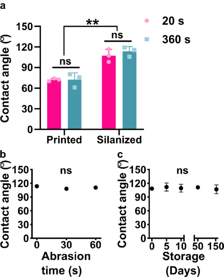
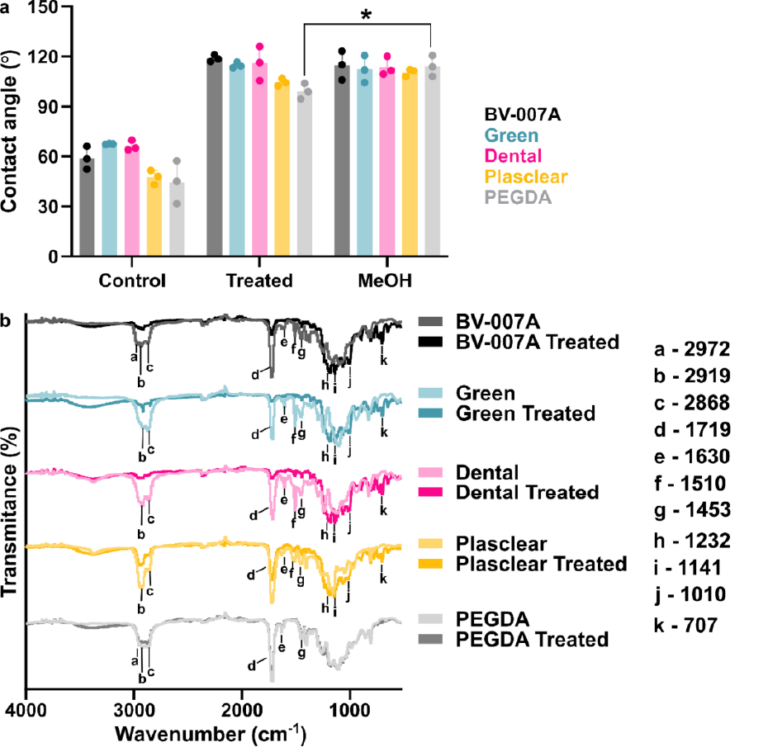
Figure 3: Robustness of the method to the age of the printed piece, abrasion, and storage time after silanization. (a) Contact angle of DLP printed pieces (BV-007A) that were silanized with or without extended UV curing (n=3 printed parts for each condition, mean ± std dev). Two-way ANOVA with Tukey’s multiple comparisons (ns, p>0.05, ** p<0.005). (b,c) Contact angle of silanized BV007 after (b) deliberate mechanical abrasion under constant pressure or (c) long term storage. n=3 printed parts for each condition, mean ± std dev. Some error bars too small to see. One-way ANOVA (ns, p>0.05).
Next, we assessed the robustness of the silanized surface when subjected to mechanical damage and extended storage, a property that affects the range of potential uses, handling, and storage. Microfluidic chips must be able to withstand mild abrasion during the movement of the device, and in particular we anticipated using this method to generate fluorinated SlipChips, which rely on sliding parts past one another.11 Therefore, silanized printed pieces were subjected to gentle mechanical damage by manually rubbing the piece against a clean polystyrene surface, mimicking normal wear and tear during use. The water contact angle of the fluorinated pieces of BV-007A was not significant altered by this process (Figure 3b), indicating that the surface is stable under mild abrasion conditions. Similarly, when silanized pieces of BV-007A were stored on the bench, the contact angles remained unchanged for at least 154 days, the longest time point measured (Figure 3c). We did observe that the initial contact angle in these experiments was slightly lower than in previous experiments, which we attribute to hydrolysis of the trichlorosilane during storage because replacement of the silane stock improved the hydrophobicity (data not shown). We concluded that the silanized surface was quite stable and the method was robust to the age of the resin though sensitive to the quality of the silane stock, all of which are consistent with the formation of a covalent bond during the silanization reaction.
Patterning of surface hydrophobicity on 3D printed parts
Compared to printing with a fully fluorinated resin, site-specific patterning is an advantage of post-print modifications, offering the potential for passive fluidic control. Therefore, we tested the ability of the silanization protocol to selectively pattern hydrophobic patches on the surface of BV-007A resin, using a pair of intersecting open channels in a simple, recessed cross design. The arms of the cross were protected from the silanization using adhesive tape, while the center square was silanized to generate a pattern of four separate fluid compartments, separated by a surface tension barrier. In the non-silanized control, colored solutions pipetted into the arms of channel mixed readily in the center of the cross (Figure 4a, Not Treated), whereas a micropatterned hydrophobic patch in the center of the cross successfully constrained the solutions to the arms (Figure 4a, Pattern). These data demonstrate that because the silanization method requires contact of the liquid silanization solution with the printed surface, it is easily patterned by physical masking strategies to define the silanized area.
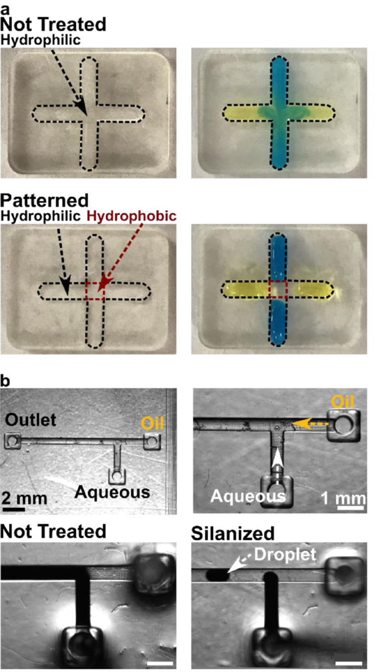
Figure 4: Application of the optimized silanization procedure for surface patterning and droplet generation. (a) Selective surface patterning of an open channel. Parts printed in BV-007A were patterned so that the center of the cross was hydrophobic. In a non-silanized piece (top), the blue and yellow food dyes mixed in the center; in the piece patterned by local silanization (bottom), the droplets remained distinct from each other. The width of the channels in these photos was 2 mm. (b) Fluorination of 3D printed fluidic channels in a T-junction droplet generator. (Top row) Photos of empty 3D printed chip at low and high magnification, with inlets and outlet marked. (Bottom row) Images of two-phase fluid flow with and without silanization of the interior channels. The dark liquid is the aqueous solution; the fluorinated oil is colorless. Droplets formed only in the silanized system. Scale bar 1 mm.
Silanization of an enclosed channel for droplet formation
In addition to surface features, many microfluidic devices feature enclosed channels whose surface chemistry must be controlled, e.g. to present a fluorophilic interior surface for droplet microfluidics.54 We reasoned that the liquid-based silanization described here to could be used to fluorinate enclosed channels by simply filling the channel with silanization solution for 30 min and rinsing afterwards; no prior surface oxidization is needed. To test this prediction, a simple T-junction droplet generator was printed (Figure 4b) and used to create water-in-oil droplets using an aqueous solution of Fe(SCN)32+ and fluorinated oil. As expected, when the 3D printed device was not silanized, the aqueous solution wetted the channel and droplets did not form (Figure 4b, Not Treated), whereas fluorosilanization by this protocol prevented wetting and enabled the formation of droplets (Figure 4b, Silanized).
Silanization of a suite of SLA resins demonstrates broad applicability
This silanization protocol would be most useful if applicable across a variety of SLA and DLP resins. Therefore, in addition to BV-007A, we tested three commercially available resins: Dental (FormsLab), Green Master Mold resin (CADworks3D), and Plasclear (iMakr), plus a polyethylene glycol diacrylate (PEG-DA)-based resin developed by the Folch laboratory.38 The resins chosen come from 3 different companies and span a breadth of applications (PDMS mold, dentistry, small part/figurine prints) and properties (low viscosity/high resolution, biocompatible, heat stable) of interest to microfluidic device fabricators. Based on our prior data that the extent of reaction correlated with diminished absorbance from the carbonyl in the IR spectrum, we hypothesized that any resin with an acrylate (BV007A and PEG-DA) or methacrylate (Dental, Green Master Mold, and Plasclear) backbone, or possibly with carbonyl-containing photoinitiators or photoabsorbers, would react with the fluoroalkyl silane. Following the optimized protocol, all printed pieces were submerged in a 10% (v/v) solution of fluorinated silane in FC-40 oil for 30 min, without plasma treatment. This procedure successfully increased the contact angle for each material compared to its non-treated control (Figure 5a). The Green Master Mold, Dental, and BV007 resins were highly hydrophobic after silanization, with contact angles of ~ 115–118°. In contrast, the PEG-DA and Plasclear resins had a mildly hydrophobic contact angle, near 100°. This trend was reproduced in two independent experiments.