Rapid manufacturing of flexible microstructured pdms substrates, using 3d DLP printing technique, for flexible pressure sensors
Florian PISTRITU , Mihaela CARP , Violeta DEDIU , Catalin PARVULESCU , Marian VLADESCU6, Paul SCHIOPU
In this work, we have carried out research on the microstructured substrates obtained with molds made by the 3D DPL printing technique, in order to obtain a microstructured substrate with maximum displacement. Microstructured PDMS and PDMS/aerogel substrates were tested. Compression tests were performed at 80N, 100N and 120N force The PDMS pyramid-type microstructured substrates, having the side of the base and the height of the pyramid of 1500µm x 1060µm, respectively 2000µm x 1414µm, obtained the best value for displacement. The better results obtained make the PDMS/aerogel composition appropriate to be used as sensitive elements/membranes in pressure sensors.
Keywords: flexible substrates, microstructured PDMS, 3D printing technique, rapid manufacturing, flexible pressure sensor
Introduction
Flexible pressure sensors are mainly used in robotics and medicine. These sensors have found applicability in various fields such as displays [1], robotics [2, 3, 4, 5], human pulse waveform [6,7,8, 9], very sensitive pressure detection [3, 8, 10], voice recognition [10], gas flow monitoring [3,8,10, 11], human-machine interface technologies [3,4,5,9], foot pressure [3]. In the field of medicine, the most used detection methods, of a pressure sensor, are based on the piezoresistive and capacitive effect [12]. The piezoresistive detection method is based on the piezoresistive effect and consists in the conversion of the deformation of a material into a variation of the resistivity, which can be measured. Depending on the application chosen for the pressure sensor, the most important parameters of the pressure sensor is also established, such as response time, sensitivity, measurement range, elasticity, bending resistance, transparency, and cost.
For a low-price method of obtaining a pressure sensor, inkjet printing technology can be used. A pressure sensor made through this technology involves the integration of a flexible substrate with an elastomeric substrate. The flexible substrate can be PET, Kapton or something similar on which it is deposited by inkjet printing, a resistor. Among the materials used for the production of the elastomeric substrate are polydimethylsiloxane (PDMS) [7, 13] and Ecoflex [14], polyethylene terephthalate (PET) [15], polyethylene (PE), polyurethane (PU), polyimide (PI) [16], and others.
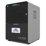
In this work, we conducted research on the microstructured substrates obtained with molds made by the 3D printing technique. The duration to obtain a microstructured substrate, through this method, is relatively short (from the 3D CAD modeling to obtaining the microstructured model from PDMS: 4 hours), offering the possibility of rapid modification of microstructure configurations. The purpose of this research is to obtain a microstructured substrate with as much displacement as possible. Integrating this microstructured substrate into a pressure sensor, we have the possibility to measure high pressures. For the realization of the microstructured substrate, Fig. 1 shows the stages from concept to test bench. In the first stage, E-I, we must have software for creating 3D CAD mold models, installed on a PC. Stage II, E-II, includes the creation of 3D CAD models of the molds. The transfer of these 3D CAD models of the molds to the 3D printer and their printing represents Stage III, E-III. After 3D printing, in Stage IV, E-IV, we have the treatments applied to the obtained 3D molds. In Stage V, E-V, we obtain the microstructures from PDMS using the molds obtained in the previous stages. In the last stage, Stage VI, E-VI, we will test these structures with the Mecmesin MultiTest 2.5 i device. When creating the 3D CAD model of the mold, we took into account the type of printer used, CADworks3D µMicrofluidics M50. The resin used to make the molds is Master Mold Resin for PDMS devices. Thus, having the printed mold, we investigated the displacement for microstructured structures from PDMS, but also PDMS/aerogel in two ratios.

Materials and Methods
2.1 Molds fabrication - Desing and printing of 3D molds
The elastomeric layer was made from PDMS, this being a silicone rubber used in the field of electronic devices. PDMS is a low-cost, low hardness elastomer, it’s a biocompatible material [17, 18], preferred for medical applications.
Several studies on the geometric variation of the microstructured PDMS layer are published in the specialized literature [20]. This microstructured layer is based in most cases on micro-cylinders, micro-pyramids, micro-domes [8]. The analyzes carried out by several authors, on different types of structural models, have shown superiority in terms of sensitivity [19] of micro-domes and micropyramid structures in relation to other structures.
From the more detailed analysis carried out in 2018 by Shuangping Liu and Monica Olvera de la Cruz [22], we observe that the thickness of the base of the micropyramids in the elastomeric layer does not have a significant influence, so we eliminated this parameter from the analysis of the structural models.
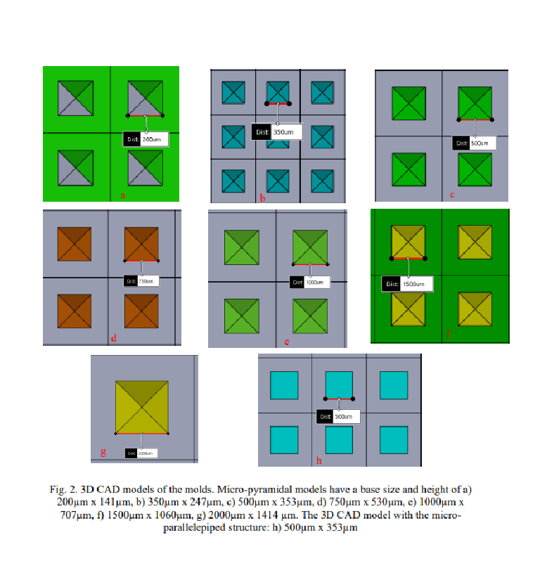
Seven 3D CAD mold models were made for the fabrication of pyramidtype microstructured substrates, and one mold model for obtaining a parallelepiped-type microstructured substrate. The general rule for all 8 types of molds was that the size of the base of the microstructure should be equal to the distance between the microstructures in all directions. Pyramid microstructures were made with base side x height of: 200µm x 141µm (P200), 350µm x 247µm (P350), 500µm x 353µm (P500), 750µm x 530µm (P750), 1000µm x 707µm (P1000), 1500µm x 1500µm (P1500), 2000µm x 1414µm (P2000). The microstructures of the parallelepiped type had a base side of 500 µm and a height of 353 µm (D500). Fig. 2 shows the 3D CAD models of the molds.

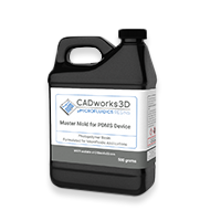
The stages of making the 3D mold are: 1) Design a 3D CAD model of the mold. The software used is FreeCAD. Execution time: 20 minutes; 2) Preparing the 3D printer for making the mold. The 3D printer used is CADWORKS3D - µMicrofluidics M50; 3) Transferring the file with the mold model from the PC to the 3D printer. The software used for the transfer is Utility 6.0. 4) Making a 3D mold. The resin was used: Master Mold for PDMS Devices – 3D Printing Resin Photopolymer Resin (Composition: Methacrylated oligomer, Methacrylated monomer, Photoinitiator & Additives). Time needed to print: approximately 15 minutes; 5) UV treatment for the printed model. After printing, the mold was cleaned in isopropyl alcohol (Isopropyl Alcohol- IPA, concentration 99.9%) twice for one minute. After cleaning in alcohol, they were dried. Then a UV treatment was performed for 20 minutes for each of the 2 faces.
2.2 Realization of the microstructured layer from PDMS
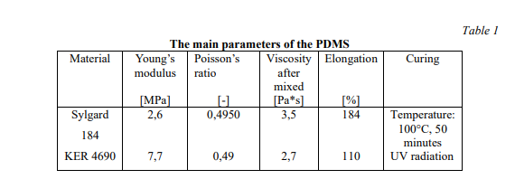
After obtaining the 3D CAD molds, the next import step is the choice of the elastomeric material to be poured into the obtained molds. Two types of PDMS were used: Sylgard 184 from DOW Chemical Company and KER 4690 from Shin-Etsu Chemical Company. These two types of PDMS are different both in terms of the modulus of elasticity and the method of exposure for curing. The steps for obtaining the microstructured PDMS substrate are: 1) mold cleaning with isopropyl alcohol IPA and drying with a nitrogen gun; 2) obtaining PDMS mixture. To prepare Sylgard 184, the mixing ratio between polymer and hardening agent is 10:1 [21], being one of the best mixing ratios. Homogenization time: 20 minutes. To prepare KER 4690, I mixed the two components KER 4690- A and KER 4690-B in a 1:1 ratio for 20 minutes.; 3) degassing PDMS mixture: for 45 min; 4) PDMS deposition on the mold; 5) Treatment for curing.
The curing treatment for Sylgard 184 consisted of exposure to a temperature of 100 C for 50 minutes, and for KER 4690 it consisted of exposure to UV radiation.
The 3D CAD models of the pyramid-type and parallelepiped-type microstructured substrate can be seen in Fig. 4 and Fig. 5


2.3 Realization of the microstructured layer from PDMS/aerogel
The PDMS used was Sylgard 184 from DOW Chemical Company. The aerogel used is powder aerogel (Powder aerogel <0.125 mm - Green Earth Aerogels).
The steps for obtaining the microstructured substrate from PDMS/aerogel are: 1) mold cleaning with IPA isopropyl alcohol and drying with a nitrogen gun; 2) obtaining the PDMS mixture. For the preparation of Sylgard 184, the mixing ratio between polymer and hardening agent is 10:1, for 20 minutes; 3) Adding to the obtained PDMS a quantity of 5% or 10% of powder aerogel, and mixing for homogenization for 15 minutes; 4) degassing PDMS mixture for 45 min; 5) depositing the PDMS/aerogel mixture on the mold; 5) Treatment for hardening at a temperature of 100°C for 50 minutes.
Results
14 types of microstructured PDMS substrates and 4 types of microstructured PDMS/aerogel substrates were tested. Compression tests were performed at 80N, 100N and 120N. In Table 1, you can see a comparison of several parameters for the two types of PDMS used.

The characterization of all microstructured substrates was carried out on the Mecmesin MultiTest 2.5i device. With the help of this device, we analyzed the compression of the microstructured substrates when applying a force of 80N, 100N, and 120N, at a compression speed of 1mm/min. Compression tests were performed using Emperor Force software. At the end of the test, the software generates an analysis report.
In Table 2 you can see the results when applying a force on a type of microstructured substrate and the displacement obtained.

In Tables 3 and 4 you can see the results obtained for different types of micro-pyramidal substrates when applying a force of 100N and 120N.


In Table 5, the results obtained from the compression of the pyramidaltype microstructured substrates made of both PMDS and PMDS/aerogel are presented.

The tests performed at a compression of up to 80N showed that the microstructured substrates made of PDMS Sylgard 184 have a greater displacement than those made of PDMS KER 4690

The highest displacement values were obtained for the micromicrostructured P1000, P1500 and P2000 substrates, which is why we performed the tests by increasing the compression force to 100N. The displacement obtained when applying a force of 100N on the substrates P1000, P1500 and P2000, can be seen in the diagram from Fig. 6.

According to the obtained results, it appears that the micromicrostructured substrates P1500 and P2000 have the best movement. Additional tests were performed only with these two types of structures, at a compression force of 120N. The results are roughly equal, with a slight edge for the P2000. By introducing aerogel into the PDMS composition, the results showed higher obtained values. The displacement obtained during compression for the microstructured substrates made of PDMS and PDMS/aerogel can be seen in the diagram in Fig. 7.


