Design and characterization of a 3D-printed staggered herringbone mixer
Vedika J Shenoy , Chelsea ER Edwards , Matthew E Helgeson & Megan T Valentine
3D printing holds potential as a faster, cheaper alternative compared with traditional photolithography for the fabrication of microfluidic devices by replica molding. However, the influence of printing resolution and quality on device design and performance has yet to receive detailed study. Here, we investigate the use of 3D-printed molds to create staggered herringbone mixers (SHMs) with feature sizes ranging from ∼100 to 500 μm. We provide guidelines for printer calibration to ensure accurate printing at these length scales and quantify the impacts of print variability on SHM performance. We show that SHMs produced by 3D printing generate well-mixed output streams across devices with variable heights and defects, demonstrating that 3D printing is suitable and advantageous for low-cost, high-throughput SHM manufacturing.
We kindly thank the researchers at University of California for this collaboration, and for sharing the results obtained with their system.

Method Summary
We investigate the use of 3D printing to create staggered herringbone mixers (SHMs) and show that such devices generate well-mixed output streams across devices with variable heights and defects. This demonstrates that 3D printing is suitable and advantageous for low-cost, low-effort, high-throughput micromixer manufacturing.
Keywords: 3D printer,calibration 3D printing, microfluidics,micromixers, staggered herringbone mixer
Microfluidic mixers such as the staggered herringbone mixer (SHM) [1] promote eddy-like mixing of laminar flow streams, avoiding prohibitively long channel lengths and enabling applications in drug delivery and discovery [2], chemical synthesis [3], sample concentration [4] and biological analysis [5–7]. In SHMs, asymmetric herringbone grooves embedded in the floor or ceiling of the rectangular channel cause transverse flow within fluid streams, promoting mixing by increasing local vorticity (Figure 1) [1,8]. Alternating the grooves' offset between cycles increases flow irregularity, further mixing the two streams [9]. The SHM's mixing proficiency and mechanism has been characterized extensively [8,10] due to its efficiency and ease of design compared with other grooved micromixers [11]. Their low shear flow properties [6] and ability to circulate flow within the channel [4] make SHMs particularly advantageous for biomedical applications,
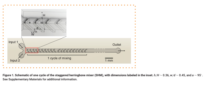
h/H ∼ 0.36, w/d ∼ 0.45, and a ∼ 95°. See Supplementary Materials for additional information.
Despite these advantages, the widespread use of SHM devices for on-chip diagnostics [4,6,12] is hindered by the reliance on time-intensive photolithography-based fabrication to generate molds for polydimethylsiloxane (PDMS)-based microfluidic devices. Photolithography requires cleanroom training and costly equipment and reagents [13]. Consequently, 3D printing is emerging as an attractive substitute for photolithography due to its comparative affordability, simplicity [14], and the ease of fabricating multilevel designs [13]. 3D printing also enables rapid prototyping by reducing typical fabrication times from days to hours [14].
To establish the use of 3D printing to generate molds for PDMS-based microfluidic devices such as the SHM micromixer, experimental validation of printer and device performance is required. For current 3D printers [15], the minimum feature size is significantly larger than that provided by photolithography, print-to-print variability is expected and random disfigurations can occur, all potentially influencing device performance. Moreover, there are often discrepancies between the targeted and actual dimensions of the 3D printed parts [16]. Unfortunately, not only is information concerning such limitations generally unavailable for any given 3D printer model, but the lack of reporting on chip-to-chip variability is a known barrier for large-scale manufacturing of microfluidic devices [17]. Thus, understanding how print quality influences pattern transfer and mixing performance is especially important for low-cost, low-effort manufacturing that maintains efficacy, as required for microfluidic diagnostic platforms.
To experimentally investigate print quality, we printed a series of raised channels, with heights and widths ranging from ∼25 to 700 μm, using a Miicraft Ultra 50 3D digital light processing (DLP) printer, with a horizontal and vertical resolution of ∼30 μm and ∼5 μm, respectively, and using Resin Works 3D Master Mold Resin for PDMS. We sized the 3D-printed parts by imaging with a Keyence VHX-5000 microscope (Supplementary Figure 1), and found them to be consistently smaller than the programmed design dimensions, with greater discrepancies in height than in the planar dimensions. These differences were consistent across all printed molds, so the programmed design dimensions could be calibrated to achieve printed parts with the correct size (Supplementary Figure 2).
This calibration critically informed mold design, which was performed in Solid Works. Features with design dimensions ≥120 μm (∼100 μm actual dimension) were reproducibly printed, whereas features with smaller design dimensions were often deformed or occasionally missing. We then printed a series of herringbone grooves with a fixed width w of 100 μm and herringbone spacing d that varied from 50 to 500 μm (Figure 1). Printed grooves with designed d < 300 μm (∼220 μm real spacing) frequently fused with the adjacent herringbones, with increasing severity for decreasing d (Supplementary Figure 1A & B). We note that these disfigurations existed within the molds themselves, not only the PDMS replicates. Thus, we established a minimum feature size of 100 μm and fixed d = 300 μm in the design of SHM molds for further study.
These constraints required SHM features in 3D-printed molds to differ somewhat from the geometries recommended by prior work [18], which find mixing to be most effective near w/d ∼1 and w = 50 μm. By contrast, our mixer has w/d ∼ 0.45 and w = 100 μm. However, we achieved a ratio of herringbone height h to channel height H, h/H ∼ 0.36, and herringbone angle a ∼ 95°, the latter of which was informed by computational work that suggested that angles in the range of ∼90°–105° produce optimal transverse flow [1,19]. Ten herringbones per each half cycle were included in accordance with prior experimental studies [10]. To compensate for the larger feature sizes and spacing requirements of 3D-printed molds and prevent the microchannel length from being excessively long, we limited the number of mixing cycle elements to five on a single chip (total channel length ∼41 mm) (Supplementary Figure 3). We then investigated a range of flow rates to produce well-mixed streams with these larger dimensions.
To demonstrate the mixing capabilities of PDMS-based micromixer devices generated using the 3D-printed SHM molds, we examined the mixing performance of two exemplar devices generated with two identically designed, but individually printed, molds. In detail, PDMS, obtained as commercially available Sylgard 184 (Dow Chemical, MI, USA), was mixed at a 10:1 ratio of PDMS to cross-linker, poured in the treated molds, degassed for approximately 2 h, then cured at 60–80°C for 4 h and removed from the mold. We did not observe qualitative deviations in the PDMS replicates formed from either mold, consistent with the well-established high-fidelity pattern transfer from 3D-printed molds to PDMS [20]. Each device was tested at flow rates from 0.5 to 20 μL min-1, corresponding to Peclet numbers Pe = 200–8000, a useful range for low shear-stress mixing of biological materials [21]. The Peclet number describes the ratio of advective to diffusive transport and is given by Pe = uL/D where u is the average velocity defined by u = q/WH and q is the volumetric flow rate, L is a characteristic length scale given here by W/2 and D is the Stokes–Einstein diffusivity.
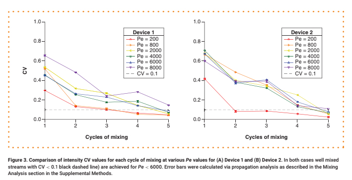
For each test, a 0.30 μM aqueous solution of 70 kDa fluorescein isothiocyanate (FITC)-dextran was delivered into Input 1, while neat water was delivered into Input 2 at an equivalent flow rate. The mixing of the two streams under steady-state flow conditions was observed via fluorescence microscopy (see Supplementary Materials for details). Representative intensity maps of the flow fields along a cross-section of the channel after one, three and five mixing cycles are shown in Figure 2. For quantitative analysis, the intensity was normalized by dividing by the maximum value (Supplementary Figure 4), and its coefficient of variation (CV), defined as the standard deviation divided by the mean, was calculated (Figure 3 & Supplementary Figure 5). We consider any profile with a CV < 0.1 to be well mixed [10].
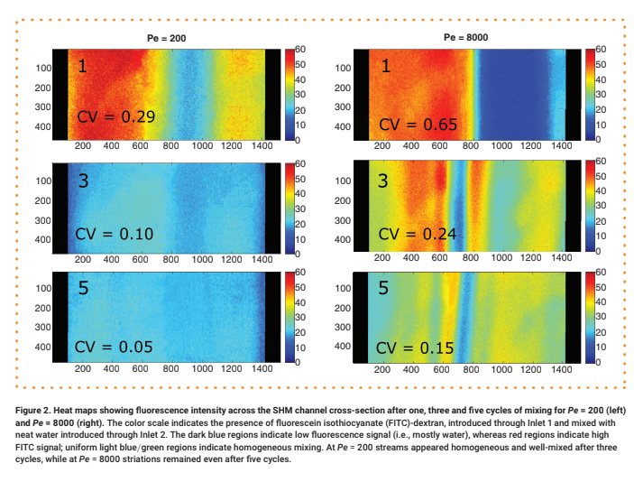
The color scale indicates the presence of fluorescein isothiocyanate (FITC)-dextran, introduced through Inlet 1 and mixed with neat water introduced through Inlet 2. The dark blue regions indicate low fluorescence signal (i.e., mostly water), whereas red regions indicate high FITC signal; uniform light blue/green regions indicate homogeneous mixing. At Pe = 200 streams appeared homogeneous and well-mixed after three cycles, while at Pe = 8000 striations remained even after five cycles.
Devices generated using 3D-printed SHM molds demonstrate good mixing performance. The number of cycles required to achieve good mixing depends on Pe, as expected. At Pe = 200, where diffusion is prominent, only three mixing cycles are required to achieve CV < 0.1, and only four to five mixing cycles are needed at Pe values of 800–6000 (Figure 3). We could not achieve good mixing for Pe > 6000 with this design due to the limited channel length. We observed a modest decline in mixer performance compared with that of devices with smaller feature sizes achieved via photolithography, where it is possible to achieve CV < 0.1 with two mixing cycles at Pe = 625 and with five cycles at Pe = 6250 [10].