A modular 3D printed microfluidic system: a potential solution for continuous cell harvesting in large-scale bioprocessing
Lin Ding, Sajad Razavi Bazaz, Mahsa Asadniaye Fardjahromi, Flyn McKinnirey, Brian Saputro, Balarka Banerjee, Graham Vesey & Majid Ebrahimi Warkiani
Microfluidic devices have shown promising applications in the bioprocessing industry. However, the lack of modularity and high cost of testing and error limit their implementation in the industry. Advances in 3D printing technologies have facilitated the conversion of microfluidic devices from research output to applicable industrial systems. Here, for the first time, we presented a 3D printed modular microfluidic system consisting of two micromixers, one spiral microfluidic separator, and one microfluidic concentrator. We showed that this system can detach and separate mesenchymal stem cells (MSCs) from microcarriers (MCs) in a short time while maintaining the cell’s viability and functionality. The system can be multiplexed and scaled up to process large volumes of the industry. Importantly, this system is a closed system with no human intervention and is promising for current good manufacturing practices.
Introduction
Microfluidics, a science of precise fluid handling within the network of channels, has shown great promise in manipulating cells and particles. Microfluidics has attracted significant attention in biology and medical research due to their unique features including low price, high throughput, high customisability, and energy-efficiently compared to other technologies (Wang and Dandy 2017; Figeys and Pinto 2000). For example, micromixers have been used in chemicals synthesis and microparticle coating (Vasilescu et al. 2020). Multiple microfluidic devices, especially spiral microfluidic channels, have been demonstrated to separate or concentrate cells based on particle sizes (Xiang et al. 2019; Nivedita et al. 2017). To date, microfluidic devices are widely used in laboratories but one of the major limitations for applying microfluidics in the industry is its customisability (Yi-Qiang et al. 2018). For instance, in the stem cell bioprocessing industry, each company has its own manufacturing protocol. The lack of standard procedure is one of the reasons for the low yield of cell products and the inconsistent clinical outcome of stem cell therapy (Jossen et al. 2018; Schnitzler et al. 2016). Although microfluidic devices have been applied in the stem cell bioprocessing industry as cell separator and concentrator in a labour-free, low-cost, and high-throughput manner (Moloudi et al. 2018, 2019), the lack of modularity and integrity makes them hard to be applied in the bioprocessing industry. Microfluidic devices are normally made from polydimethylsiloxane (PDMS) by soft lithography. Compiling these single microfluidic devices together to increase the throughput requires multiple external tubing and diverters to meet the industrial need, and testing and modifying them to meet the demand requires a huge amount of time and effort. 3D printing technology can be a good solution for this inadequacy. In recent years, the advances in 3D printing technologies have made it increasingly appealing for producing microfluidic devices (Bhattacharjee et al. 2016). The resolution of 3D printing allows direct construction of microfluidic channels with micrometre-level features, and the study and treatment of 3D printed resin enable the production of soft-lithography mould in a few hours (Vasilescu et al. 2020; Razavi Bazaz et al. 2019). Although 3D printing technologies are not the solution for large-scale manufacturing of microfluidic devices, their potential to modify changes and fabricate microfluidic devices in a few hours is unique and valuable for the industry. This feature hugely decreases the cost and time needed for rapid prototyping and building integrated microfluidic systems.
In the stem cell industry, microcarriers (MC)-based culture systems are a promising candidate for maximising cell manufacturing on a large scale. MCs facilitate massive cell expansion at a lower cost and allow control of cell culture parameters in a homogenous condition to produce consistent quality cell products at a large scale (Fardjahromi et al. 2020; Chen et al. 2020). Despite the enormous advantages of microcarrier-based technologies in maximising cell production, harvesting cells from MCs still faces challenges with high product quality and yield (Chen et al. 2013). The common method for harvesting is detaching cells with digestive enzymes and separating them from MCs using membrane-based filtration or centrifugation (Chilima et al. 2018; Tavassoli et al. 2018). Membrane-based filtration separates the cells with a physical porous filter. Clogging filters is the major limitation of this method (Schnitzler et al. 2016; Zydney 2016). In addition, membrane fouling has been shown to cause cell death, cell fate changes, and reduce the therapeutic potential of harvested cells (Chilima et al. 2018; Zydney 2016; Rodrigues et al. 2018). Centrifugation-based methods, particularly continuous flow centrifugation, are another alternative method for separating cells from MCs (Schnitzler et al. 2016). The advantage of this method is that it washes cells during separation, but the centrifugation process is time-consuming, potentially causing cell damage (Joseph et al. 2016). In addition, the continuous washing and centrifuging process cost more reagents and disposables (Serra et al. 2018). Hence, a continuous, clogging-free, highly efficient, and low-cost harvesting method is severely lacking in this area.
Herein, in this paper we report an integrated 3D printed modular microfluidic system containing two micromixers, one spiral separator, and one zig-zag concentrator. We used this system to detach and separate mesenchymal stem cells (MSCs) from MCs and eventually concentrate them in a smaller volume for downstream processing. At first, each module was characterised using cells and microbeads in different volume fractions and flow rates to obtain the optimum condition for the MSC harvesting. Then, the viability, proliferation, and therapeutic properties of MSCs harvested with our proposed integrated system were compared with the manual method, i.e., Millipore filtration. The results indicate that the developed microfluidic device is a promising candidate for automated MSCs harvesting and concentrating from MCs. In the end, we demonstrated that the system could be multiplexed to process samples with higher throughput.
Materials and methods
Device fabrications
Figure 1A depicts the general concept of unidirectional imaging. To create a unidirectional imager using reciprocal structured materials that are linear and isotropic, we optimized the structure of phase-only diffractive layers (i.e., L1, L2, …, L5), as illustrated in Fig. 1 (B and C). In our design, all the diffractive layers share the same number of diffractive phase features (200 by 200), where each dielectric feature has a lateral size of ~λ/2 and a trainable/learnable thickness providing a phase modulation range of 0 to 2π. The diffractive layers are connected to each other and the input/output FOVs through free space (air), resulting in a compact system with a total length of 80λ (see Fig. 2A). The thickness profiles of these diffractive layers were iteratively updated in a data-driven fashion using 55,000 distinct images of the MNIST handwritten digits (see Materials and Methods). A custom loss function is used to simultaneously achieve the following three objectives: (i) minimize the structural differences between the forward output images (A → B) and the ground truth images based on the normalized mean square error (MSE), (ii) maximize the output diffraction efficiency (overall transmission) in the forward path, A → B, and (iii) minimize the output diffraction efficiency in the backward path, B → A. More information about the architecture of the diffractive unidirectional imager, loss functions, and other training-related implementation details can be found in Materials and Methods. After the completion of the training, the phase modulation coefficients of the resulting diffractive layers are shown in Fig. 2C. Upon closer inspection, it can be found that the phase patterns of these diffractive layers have stronger modulation in their central regions, while the edge regions appear relatively smooth, with weaker phase modulation. This behavior can be attributed to the size difference between the smaller input/output FOVs and the relatively larger diffractive layers, which causes the edge regions of the diffractive layers to receive weaker waves from the input, as a result of which their optimization remains suboptimal.For the fabrication of microfluidic devices using additive manufacturing, different techniques exist. Fused Deposition Modelling (FDM), Stereolithography (SLA), Digital Light Processing (DLP), two-photon polymerisation (2PP), Multijet, and wax printing are all capable of fabricating microfluidic devices. For the creation of complex microfluidic devices, however, DLP and wax printing methods show more promise in this regard. The fabrication process of these two methods is illustrated in Additional file 1: Fig. S1. The wax 3D printing method is a multi-step process, and the printed microfluidics are inherently fragile and prone to fault and error. As an alternative, DLP method has been selected for the current study because of its accuracy, precision, fast turn-around time, and the ability to fabricate robust complex microfluidic channels (Chai et al. 2021; Ding et al. 2022). Design selection consideration is introduced in detail in Additional file 1: Section S1.
The micromixers were designed in Solidworks 2018 × 64 edition (SolidWorks Corporation, USA) and fabricated with a high-resolution DLP resin printer (MiiCraft II, Hsinchu, Taiwan), with the layer thickness of 50 µm. BV-007 resin was used, which is an acrylate-based resin containing 80–95% acrylate components and 10–15% photoinitiator and additives (Razavi Bazaz et al. 2020a). After printing, the micromixers were carefully removed from the build plate, washed with isopropyl alcohol, and dried by air nozzle. This process was repeated three times to prevent uncured resin from clogging the channels. Then, the micromixers were cured by 450 nm UV light in a UV-curing chamber. The design and dimension of the micromixer are shown in Additional file 1: Fig. S2.
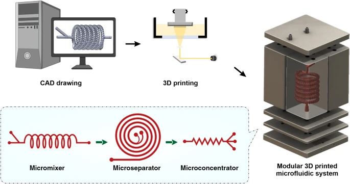
The spiral chip and zig-zag channel were produced as previously described (Razavi Bazaz et al. 2020a; Ding et al. 2022). Briefly, the devices were designed by SolidWorks and printed by the MiiCraft II 3D printer with a 10-µm layer thickness. Then the devices were rinsed with IPA and dried with an air nozzle three times. These devices were further post-processed by UV light in a UV-curing chamber and then bound to a PMMA sheet with a double-sided tape (ARclear®, Adhesive Research). Next, Tygon tubes (Tygon tubing, inner diameter: 0.50″, outer diameter: 0.90″) were used as connections of inlets and outlets to connect each part. Finally, the printed parts were then connected in series, as shown in Fig. 1.
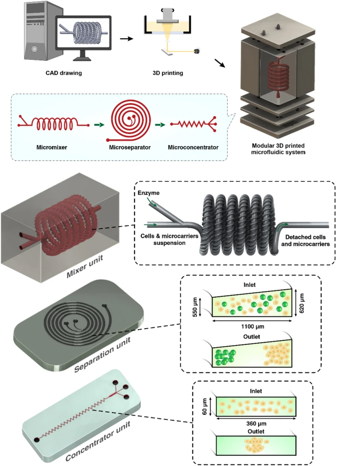
Schematic representation of the modular microfluidic system. The whole system was built by 3D printing technology. The system comprises two micromixers, a micro separator, and a zig-zag channel connected vertically to detach cells from MCs, separate cells from MCs, and dewater the harvested cells. The adherent cells on MCs were detached from MCs through enzymatic treatment and gentle mechanical force inside of mixer channels. Cells and MCs were then collected separately from spiral outlets and concentrated using the zig-zag concentrator unit. The dimension of the micromixer is shown in Additional file 1: Fig. S1
Characterisation of micromixer module
The performance of the micromixer has been evaluated using numerical (described in detail in Additional file 1: Sections S2, and S3 explained the detail of mixing index calculation) and experimental results. To verify the mixing efficiency of the mixers, food dye (1 mL in 49 mL DI water) and pure DI water were loaded in 50-mL syringes and injected into the mixer with syringe pumps at different flow rates. The syringes were connected to the Tygon tubes with precision syringe tips (0. 0. 50″ Long Tip, Adhesive Dispensing Ltd, UK). The pictures of the mixed liquid before and after going through the mixing units were taken by Olympus IX73 microscope (Olympus, Japan). The pictures were then analysed, and the degree of experimental mixing efficiency in these channels was compared with numerical results obtained using COMSOL Multiphysics (Razavi Bazaz et al. 2020b) (refer to Additional file 1).
Characterisation of the microseparator module
Star-Plus MCs (Pall, SoloHill) were used to characterise the microseparator module. A spiral-shape microchannel was used for this purpose since it is capable of high-throughput and continuous sample processing without clogging issues (Moloudi et al. 2018). MCs were diluted in MACS buffer (Miltenyi Biotec, Australia) to acquire different volume fractions (0.1, 0.25 0.5, 0.75, 1% v/v%). The videos of particle movement were recorded by Phantom High-Speed camera (Phantom Academy, USA). The first 2000 frames of the video were stacked by ImageJ to observe the trajectory of the movement of the beads.
Characterisation of the microconcentrator module
To concentrate the collected MSCs, a zig-zag microfluidic channel was designed and tested. Based on the spiral outlet dimensions, the input flow rates of the zig-zag channel were calculated (~ 1.6–1.8 mL/min). As such, 15 µm microbeads (PMMA (polymethyl methacrylate) latex beads, Magsphere, USA) were used to characterise different zig-zag channels with different dimensions. To this end, 50 µL microbeads were added into 10 mL MACS buffer and loaded into a 10-mL BD plastic syringe (BD, Australia). The microbeads were pumped through the device, and high-speed camera videos were recorded and evaluated.
Microfluidic-based cell harvesting system setup
The modular 3D printed microfluidic system was set up with two micromixers, a spiral microfluidic device, and a zig-zag concentrator connecting in series with Tygon tubes. Cell harvesting was conducted in a biosafety cabinet to prevent any contamination. The upper mixer has two inlets, one was connected to the bioreactor through a peristaltic pump (Shenchen, China), and the other one was connected to a syringe pump (Fusion Touch, Chemyx Inc) for the TrypLE injection. Before cell harvesting, the whole setup was sterilised by 70% ethanol and UV irradiation. The same number of cell-attached MCs was harvested by the conventional membrane filtration method as a control. Briefly, the MCs were allowed to settle for 10 min, and then the culture media was carefully removed by a serological pipette. 40 mL of TrypLE was added to the bioreactor and incubated for 20 min. The microcarrier-cell suspension was gently pipetted before filtration. Lastly, the suspension was filtered by Steriflip Nylon Net filters (Millipore Steriflip filtration 100 μm, Merck, Australia), and the filtrated cells were collected. The recovery rate of cells and microcarriers were calculated by: R=Ntargetoutlet/(Ntargetoutlet+Noutheroutlet) , N is the number of particles counted with haemocytometer. Counting was repeated 3 times.
Cells culture and cells characterisation
Cells culture before harvesting and cells characterisation after harvesting are described in detail in Additional file 1: Section S4 and S5.
Statistical analysis
The statistical significance in the data was calculated by Student’s t-test using Graph Pad Prism7 software. Significance levels were shown as *p < 0.05.
Results
Working principle of micromixer module
Two mixing strategies were applied in the proposed micromixer: Dean force induced by the helical 3D channel structure and the mismatch of flow rates induced by twisted helical groove structures following the 3D spiral. The first strategy creates fluid velocity mismatching in the channel’s inner side and outer side by having the curved channel, leading to the formation of two opposing vortexes in the channel and thus reducing the diffusion distance of the two fluids (Chai et al. 2021; Cai et al. 2017). For the second strategy, the twisted helical groove structure contributes to fluid mixing by creating a slow fluid flow zone and therefore inducing another mismatching of fluid velocity. This fluid mismatching carries the fluid from one side towards the other side of the channel, increasing the chance of fluids contact (Vasilescu et al. 2020; Chai et al. 2021); consequently, the increased contact of different fluids enhances the molecular diffusion. As previously reported, the groove designs in the channel would not introduce strong secondary flow (Tsui et al. 2008). Additional file 1: Fig. S3 shows the simulation results of the micromixer. Increasing the inlet fluid flow ratio leads to increased pressure in the system, which is negligible for smaller flow rate ratios and shows the system can be powered by normal lab-scale pumps. The cross-section 1 (CS1) across different flow rates in Additional file 1: Fig S3 shows that the chaotic advection phenomena dominate over diffusion when the flow rate increases. However, higher flow rate ratios do not necessitate a higher mixing index since fluids take time to mix and diffuse (Additional file 1: Fig. S3). Interestingly, velocity distribution for lower flow rates shows a symmetric profile along the channel length (Additional file 1: Fig. S3C), while it becomes asymmetric for higher flow rate ratios. This phenomenon might also contribute to the reduction of the mixing index at higher flow rates.
The experimental results of the mixing index with pure water and food dye for various flow rate ratios are illustrated in Fig. 2A. The mixing efficiency of the device was higher than 95% (Additional file 1: Fig. S5) at the flow rate ratio of 1 mL/min:2 mL/min. Hence, the total flow rate of 3 mL/min was chosen as an optimised flow rate for cell harvesting. Based on the method described in Additional file 1: Section S1, the experimental mixing index is 82.7%. The discrepancy between simulation and experimental results can be attributed to the difficulties of imaging 3D printed channels with microscopy and the addition of extra noise in the picture due to the unsmooth surface of the micromixer (Rouhi et al. 2021). The micromixers have no splitting, obstacles, or sharp turning, which are appropriate for processing cells without damaging them.
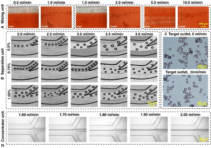
Characterisation of the microfluidic harvesting system using food dye, MCs, and fluorescent microparticles. A The micromixer reached 95% mixing efficiency with a 1:2 fluid flow mixing ratio. B The spiral microfluidic device can be operated at a flow rate of 3 mL/min with 0.75% v/v% microcarrier concentration. C The micromixers and spiral apply gentle forces to the microcarriers, and no breakage of microcarriers happened even when the flow rate was 6 times higher than the operation flow rate. D The zig-zag channel focuses 15 um beads from 1.6 to 2 mL/min with a 100% recovery rate
Working principle of the microseparator module
The focusing position of microparticles inside a curved microfluidic channel is affected by two forces, inertial lift force (FL ) and Dean drag force (FD) (Amini et al. 2014):

FL is affected by the density of fluid ρ , the hydraulic diameter Dh (which can be calculated by 4A/P , A= channel cross-section and P= perimeter of the channel), the maximum fluid velocity Umax which is approximated as 2×Uf (Uf is the average velocity), CL which is a constant named dimensionless lift coefficient number and is dependent on the channel Reynolds number (Re=ρUfDh/μ,μ is the viscosity of the liquid) and the diameter of particles a . FL consists of two forces: shear-gradient and wall-induced lift force. Shear gradient lift force pushes the particles towards the wall due to the velocity difference between the middle area and the side area of the channel. When the particles move close to the wall, the wall lift force pushes the particles away. The balancing point of inertial equilibrium position contributed to the lift force is where these two forces balance each other (Razavi Bazaz et al. 2020c).
In a curved channel, the channel’s curvature causes the inner wall (IW) fluid to flow faster than the outer wall (OW) due to the shorter distance travelled. This transverse fluid flow creates another force that affects the focusing position of the particles, which is the Dean drag force (FD ). FD is defined in Eq. (2), where De=ReDh/2R−−−−−−√ is the Dean number, and R is the radius of curvature; it describes the strength of FD . According to Eqs. (1) and (2), the forces applied to the particles are proportional to the particle size (FL∝a4,FD∝a ). Therefore, different particle sizes have different focusing positions across the channel cross-section, and they can be collected through separate outlets (Mihandoust et al. 2020; Ozbey et al. 2019).
In a normal spiral channel, the particles inside the channel need to follow the rules of Cr>0.07 , where Cr=a/Dh to be affected by the inertial forces inside the channel. In a scaled-up microfluidic channel, the increase in Dh results in a reduction of absolute flow velocity compared with a normal microfluidic channel. Therefore, the secondary forces applied to the microparticles were weaker, and the Cr value in the scaled-up microfluidic channel was much higher than the microfluidic channels (Cr>0.17) (Moloudi et al. 2019; Carlo 2009). Another factor that affects particle focusing is channel rigidness. There is no swelling or channel inflation in rigid channels compared to traditional PDMS chips; thus, the scaled-up device should have theoretically a lower Cr . Also, larger particles are more likely to be affected by mass and gravity since they are not neutrally buoyant (Moloudi et al. 2019), adding another variable despite flow velocity; the variable sizes of particles would also increase the difficulty in the channel design. When MCs and cells pass through the channels, focusing MCs near the IW causes the MSCs to be dispersed in the channel due to the large size difference between MCs and cells (MCs size are 150–220 µm, and MSCs are 15–20 µm). However, since large particles occupy the inner channel, the particle–particle interaction can stop some of the MSCs from going out through the inner outlet (Moloudi et al. 2018). Considering all these factors, in this study, we have designed the channel with a trapezoidal cross-section and heights of 550 µm and 620 µm, and a width of 1100 µm. This spiral chip has 6 loops and a slightly slanted enlarged inlet size to prevent clogging of MCs at the beginning of the channel (Fig. 1).
Working principle of the microconcentrator module
The zig-zag channel relies on inertial, and Dean drag forces to focus the MSCs at the centre of the channel. When Reynolds number of the channel falls in the intermediate range 1 < Re < 100, the fluid flow is laminar, between Stokes and turbulent flow regimes. Therefore, inertial forces focus the randomly dispersed particles toward certain equilibrium positions after a sufficiently long channel length. As explained above, shear-gradient and wall-induced lift force are the main forces affecting the particle focusing in straight channels, and they both contribute to the overall inertial lift force FL . Straight channel relies on the difference in particle sizes to focus the particles at different positions (FL∝a4 ). In zig-zag channels, Dean force FD is introduced differently compared to the spiral microfluidic channel. The interchanging channel direction creates a mismatch of fluid flow velocity in an alternating pattern and introduces Dean force, accelerating the focusing of particles inside the channel. A zig-zag channel has three focusing modes across different flow rates. When FL<FD , the particles focus at the side of the channels. When FL>FD , the particles were focused in the middle of the channel due to due to the strong FL . When FL∼FD , particles are in the transition mode. For the aim of this study, MSCs need to satisfy the condition of FL>FD. One primary advantage of the zig-zag channel is its operating ranges of flow rates, i.e., it can focus particles at the centre over a wide range of flow rates. After careful evaluations, the zig-zag channel with a cross-section of 360 µm × 60 µm, 60° angle has been proposed to concentrate cells after the spiral microfluidic device. To avoid clogging of zig-zag channels caused by the remaining MCs in the target outlet, some obstacles were planted at the target outlet of the spiral to ensure no MCs could enter the zig-zag channel.
Pressure balance of microfluidic system
ombining multiple microfluidic devices in one system requires careful arrangement to balance the fluid flow and pressure change. An electronic circuit was used as an analogy for our system to understand better the fluid behaviour in the system (Additional file 1: Fig. S5). These microfluidic devices resemble the resistors that reduce the pressure input from the pumps, similar to the voltage drop in an electronic circuit (Oh et al. 2012). Keeping the flow rate and pressure stable according to the following equation is the key point of the successful operation of this system:

where Q is the volumetric flow rate, RH is the hydraulic resistance of the channel, μ is the viscosity, Δp is the pressure drop, and L is the channel length. In a serial circuit, Q (which is current I in the electronic circuit) remains constant in each device, thus Qspiral=Qmixer1=Qmixer2 . Qmixer1 has two inputs, one from the peristaltic pump, and one from the syringe pump. In a parallel circuit, the current of the circuit Qmixer=Qinlet1+Qinlet2 . The working flow rates of micromixers and zig-zag channels are more flexible, while the spiral microfluidic device only works under a specific flow rate. To achieve this flow rate, we change the flow rate of the two pumps according to Qspiral=Qinlet1+Qinlet2 . The outlet’s resistance of the spirals affects the focusing of the MCs in the inner outlet. Therefore, the fluid pressure of the zig-zag channel must be balanced with the pressure-damping channel connecting to the inner outlet of the spiral device. This pressure-damping channel needs to have the same hydraulic resistance RH to the zig-zag channel, which can be calculated by Eq. (4) (Oh et al. 2012):

where η is the viscosity and L is the finite length of the channel. Since Dh of the channel is fixed and RH∝8L , changing the length of the pressure-damping channel to reach R3 = R4 balances the pressure of the system and would not affect the particle focusing positions in the spiral channel (Additional file 1: Fig. S6). This system potentially eliminates the debris larger than cells through spiral channel, and removes debris smaller than the cells through the zig-zag channel.
Evaluation of different modules with fluorescent microbeads and microcarriers
The maximum capacity and optimal flow rate of the spiral microfluidic device was determined by passing a different concentration of MCs through the device across a range of flow rate. As shown in Fig. 2B and Additional file 1: Fig. S6, from 2.0 to 4.0 mL/min, the focusing position of the MCs gradually shifts to the outer outlet. Noticeably, 3.0 mL/min is the critical flow rate that runs under high throughput while still focusing the MCs at the inner outlet. MCs with a concentration higher than 1% escape from the outer outlet even at a lower flow rate. However, MCs with a concentration of 0.75% can be sufficiently removed from the inner outlet at a flow rate of 3 mL/min. At the flow rate of 3 mL/min (2 mL/min from the bioreactor, 1 mL/min from the enzyme reservoir), the fluid mixing efficiency reached 95% after the first micromixer (Additional file 1: Fig. S4). The addition of the enzyme from the syringe pump inlet of the micromixer dilutes the sample.
The microcarrier concentration used for cell culture was 1.29% v/v% (1 g in 80 mL media). Therefore, MCs’ volume and concentration for cell harvesting before entering the microfluidic gadget were set to 70 mL to reach 0.75% when the sample arrived at the spiral microfluidic chip. The volume was calculated by the following equations: target concentration (0.75%)/dilution factor in micromixer (2/3)/concentration in culture (1.29%) × volume in culture (80 mL). As such, 40 mL of TrypLE was added since there was 30 mL of media inside the bioreactor after 50 mL of supernatant was taken away. The flow rate was set at 2 mL/min from the bioreactor and 1 mL/min TrypLE from the syringe pump, so the total flow rate of 3 mL/min fluid proceeded into the spiral. To demonstrate the inertial forces in the system do not damage the MCs, we passed MCs through the two micromixers and one spiral chip setup under a 20 mL/min flow rate. The results showed that the gentle forces applied by the micromixer do not change the shape and size of the MCs (Fig. 2C). Various inertial microfluidic channel designs can be used in this application as evidenced in our previous publications (Moloudi et al. 2018). In this study, we have showcased a rigid channel in the processing of large particle through the power of 3D printed inertial microfluidics. The zig-zag channel was responsible for further concentrating the harvested cells. Since it was connected to the outer outlet of the spiral, the operation flow rate of the zig-zag channel needed to match the flow rate of the outer outlet of the spiral. The zig-zag concentrator was tested with 15 and 20 µm beads across different flow rates. The results showed that from 1.6 to 1.9 mL/min, the beads were concentrated 100% in the middle outlet (Fig. 2D). The beads were concentrated ~ 3.5 times, with ~ 70% of the volume removed, indicating good dewatering efficiency of the device.
Results
Harvesting MSCs from bioreactor using the microfluidic system
To investigate the efficiency of the microfluidic gadgets on cell detachment, the cells were stained with Hoechst before passing through the mixer. To ensure the complete detachment of cells in the micromixers, a one-inlet micromixer was added at the end to increase the interaction of cells and enzyme under the same mixing efficiency (Vasilescu et al. 2020). Figure 3A shows microcarrier-cell suspension before cell harvesting in which cells covered the whole surface of MCs. The growth of healthy MSCs on MCs commonly leads to cell–MCs aggregation (Ferrari et al. 2012) (Additional file 1: Fig S7). Therefore, to prevent the blockage of microfluidic devices, the cells–MCs suspension was incubated with enzyme for 5 min in the incubator to detach these aggregates. Figure 3B shows the MSCs were detached from MCs’ surface by enzymatic treatment and gentle mechanical force after passing through the micromixers.
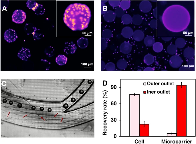
Harvesting MSCs with our microfluidic system. The concentrating efficiency of the zig-zag channel is shown in Additional file 1: Fig. S9. A and B Fluorescent microscopy images of cells–MCs before and after passing through the mixer. Cell nuclides were stained with Hoechst. C Separation of cells and microcarriers through the spiral chip. Cells and MCs were separated through different channels based on their size difference. D The recovery rate of cells and MCs after passing through the spiral chip in one round. The liquid collected from the inner outlet of the spiral was collected and performed a second-round running through to further recover the cells. The two-round separation results are shown in Additional file 1: Fig. S8
The media containing detached cells and MCs from the micromixers were then passed through the spiral. Later, they were collected separately from two outlets (Fig. 3C). 94.11% of MCs were successfully removed in the first round of separation. 76.62 ± 2.1% and 17.21 ± 0.6% cells were recovered from the OW outlet in the first and second pass, respectively, and 6.16 ± 1.80% cell loss through the IW outlet at the end of the process (Fig. 3D, Additional file 1: Fig. S8). The sum of yield (sum of cells harvested from the OW outlet over the total cell harvest from all outlets) can reach ~ 94%. Adding some obstacles at the outlet leads to 100% of the microcarrier removal rate, making it ready for clinical applications. Additional file 1: Fig. S9 shows the tight focusing band of MSCs in the middle outlet and the removal of small debris in the outer outlets. The cell solutions were collected from the outer outlets, and no cell was found in the waste outlet. Cells were concentrated 4.5 times compared to the pre-filtered samples. Although the counting results showed that the recovery rate was higher than 100%, a small number of cell loss could potentially happen due to the heterogeneity, clumping of cells, or attachment to the tubing or channel walls.
MSCs viability and proliferation after microfluidic cell harvesting
Cell viability was assessed immediately after harvesting. The live and dead staining results indicate that the microfluidic device did not compromise the viability of cells (Fig. 4A). MTS (3-(4,5-dimethylthiazol-2-yl)-5-(3-carboxymethoxyphenyl)-2-(4-sulfophenyl)-2H-tetrazolium) assay illustrating the metabolic activity of cells harvested by the device is also similar to the control. In the microfluidic group, the absorbance of media at 490 nm wavelength increased over time which indicates that cells have slightly higher metabolic activity than the control group, although the difference is not significant (Fig. 4B). Cell attachment, morphology, and proliferation were evaluated by staining the post-harvesting cells using DAPI and phalloidin. The fluorescent microscopy images in Fig. 4C and D indicate cells harvested with the microfluidic device have comparatively better cell attachment (Additional file 1: Fig. S10) than the control group on the first day of culture. After 3–5 days of culture, both groups of cells were confluent in the wells, and no significant difference in the growth rate was observed. Additionally, cells maintained their spindle morphology after harvesting with the device, and the size of cells was around 13–17 µm in both groups. The number of harvested cells after 1, 3, 5 days of cell seeding was counted by ImageJ to verify the MTS results. The results confirm that the microfluidic system does not affect cell attachment and growth after harvesting (Additional file 1: Fig. S10).
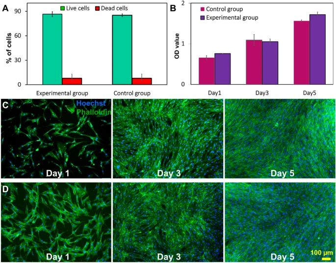
Viability and proliferation of MSCs after harvesting process. A The viability of cells harvested by the microfluidic system and filtration method. Cell viability did not change significantly compared with the control group. Data are presented as mean ± SEM (****p value < 0.0001, n ≥ 3). B MTS viability/proliferation rate of harvested cells. The morphology and proliferation rate of MSCs of the two groups were also compared with DAPI/phalloidin staining via C filtration group and D microfluidic group on 1st, 3rd, and 5th day of culture. F-actin filaments were visualised via FITC labelled phalloidin (green) and nuclei with DAPI (blue)
Stem cell properties and therapeutic properties of the harvested MSCs
To confirm the stemness and multipotency of the harvested cells, the MSC surface markers were evaluated and trilineage differentiation was performed. CD90, CD73, and CD105 were stained with fluorescent antibodies (ThermoFisher, Australia) staining and counted by a flow cytometer (CytoFLEX LX, Beckman Coulter, USA). Figure 5A shows 98%, 100%, and 100% of the cells express CD90, CD73, and CD105, respectively, confirming the well-preserved MSCs identity. To assess the multipotency of cells after harvesting, cells were stained with Oil Red, Alizarin Red, and Alcian Blue staining after treating with adipogenic and osteogenic/chondrogenic induction media, respectively (Fig. 5B). Formation of bright red stain calcium deposits stained by Alizarin Red S confirmed osteoblastic phenotype of cells. Additionally, presence of red lipid droplets stained by Oil Red O verified the adipocyte phenotype, and the blue glycosaminoglycan complex staining showed the presents of chondrogenic cells. These results indicate that cells retained their differentiation potential.
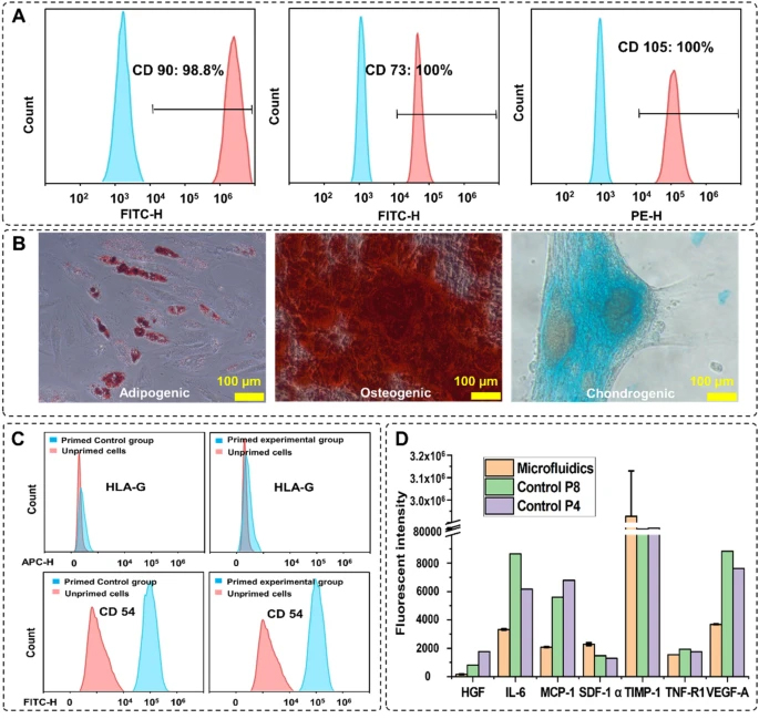
MSCs characterisation after harvesting. A Expression of the MSCs surface markers CD90, CD73, and CD105 after 3 passages of indicated cells preserve their stemness after harvesting. B Multipotency assay of harvested cells using Oil red (left), Alizarin red (middle), and Alcian blue (right) showed the cells maintained their capacity to differentiate into different cell types. C The expression level of the surface therapeutic proteins of the experimental group. The changes in the expression level of HLA-G and CD54 were similar in both groups. D Comparison of the cytokine secretion profile of MSCs harvested from the microcarriers with microfluidic system and the passage 4, passage 8 planar flask cultured cells
The therapeutic effect of harvested MSCs is verified by staining the surface therapeutic proteins and analysis of the cytokines in the cultured supernatant. Figure 5C shows the changes in the expression level of the surface therapeutic proteins after priming with TNF-α and IFN-Υ for 24 h. HLA-G is a protein that prohibits the growth of lymphocytes, which expression level does not change with priming (Nasef et al. 2007; Selmani et al. 2009; Najar et al. 2012). The expression level of HLA-G in both microfluidic and control groups remained constant after priming. CD54 (iCAM) is a T-cell activation-related protein that is sensitive to inflammation, and the expression level of this protein increased significantly after priming (Rubtsov et al. 2017; Tang et al. 2018). Figure 5C shows that the expression level of CD54 increased 100% after priming in both groups. These results prove that there is no significant difference in the therapeutic properties of the MSCs after proceeding through the microfluidic device. Next, using the Custom ProcartaPlex Multiplex immunoassay panel, we analysed the secretion profile of the harvested cells compared to the secretion profile of cells passaged stably in multilayer cell factories. The results showed that the harvested cells expressed a similar or lower level of HGF, IL-6, CCL2, VEGF-A, and TNF-RI compared to the passage 4, passage 8 multilayer cell factory grown controls, the expression level of SDF-1 alpha and TIMP-1 are much higher than the control group (Fig. 5D).
Multiplexing the microfluidic harvesting system for large-scale application
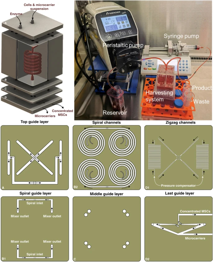
A multiplexed system was built with the same printing protocols to demonstrate the capability of scaling up the microfluidic system for large-scale applications. The system consists of five layers (Fig. 6); the first layer is the fluid splitting layer; it has one inlet for cell and microcarrier solutions to enter the system and another inlet for the digestive enzyme with a flow rate of 8 mL/min for the cell and microcarrier solution and 4 mL/min for the enzyme. These two inlets split the total flow into four even sets and enter the 4 micromixers evenly in the second layer. The micromixers have inserted holes for the pins to anchor the positions and prevent leakage. The flow rate in each micromixer is 3 mL/min for detaching cells from MCs. The third layer is the spiral layer, with a pin inserted into the outlet of the micromixers. The solutions collected from each of the two micromixers were evenly split into two spiral microfluidic devices, and each spiral received 3 mL/min liquid flow to separate cells from MCs. Then, the fourth layer, a splitting layer was used as the bottom layer of the spiral. Two holes were opened at the outlets of the spirals, and this layer was bonded with the fifth layer spiral layer with double adhesive tape. Lastly, a whole 3D printed layer with 4 zig-zag channels and pressure-damping channels was attached to the splitting layer with double adhesive tape. The inner outlets of each spiral are connected to one pressure-damping channel, and the outer outlets of each spiral are connected to one zig-zag channel. The cross-sectional area ratio of the inner and outer outlet is 2:3; the flow rate of the outer outlet is, therefore 1.8 mL/min for each spiral. As shown in Fig. 2, the zig-zag channel can focus the cells from 1.4–1.9 mL/min. This flexible working range of the zig-zag channel ensures the cells focus on the middle outlet of the device and reduce the requirement of precision of the pressure-damping channel. The total flow rate of the cell outlet was 7.2 mL/min, while the MCs outlet was 4.8 mL/min.
