3D-Printed Microinjection Needle Arrays via a Hybrid DLP-Direct Laser Writing Strategy
Sunandita Sarker, Adira Colton, Ziteng Wen, Xin Xu, Metecan Erdi, Anthony Jones, Peter Kofinas, Eleonora Tubaldi, Piotr Walczak, Miroslaw Janowski, Yajie Liang, Ryan D. Sochol
Microinjection protocols are ubiquitous throughout biomedical fields, with hollow microneedle arrays (MNAs) offering distinctive benefits in both research and clinical settings. Unfortunately, manufacturing-associated barriers remain a critical impediment to emerging applications that demand high-density arrays of hollow, high-aspect-ratio microneedles. To address such challenges, here, a hybrid additive manufacturing approach that combines digital light processing (DLP) 3D printing with “ex situ direct laser writing (esDLW)” is presented to enable new classes of MNAs for fluidic microinjections. Experimental results for esDLW-based 3D printing of arrays of high-aspect-ratio microneedles—with 30 µm inner diameters, 50 µm outer diameters, and 550 µm heights, and arrayed with 100 µm needle-to-needle spacing—directly onto DLP-printed capillaries reveal uncompromised fluidic integrity at the MNA-capillary interface during microfluidic cyclic burst-pressure testing for input pressures in excess of 250 kPa (n = 100 cycles). Ex vivo experiments perform using excised mouse brains reveal that the MNAs not only physically withstand penetration into and retraction from brain tissue but also yield effective and distributed microinjection of surrogate fluids and nanoparticle suspensions directly into the brains. In combination, the results suggest that the presented strategy for fabricating high-aspect-ratio, high-density, hollow MNAs could hold unique promise for biomedical microinjection applications.
Introduction
Microinjection technologies underlie a diversity of biomedical applications, such as in vitro fertilization, intraocular injection, therapeutic drug and vaccine delivery, developmental biology, and transgenics.[1-4] Historically, microinjection protocols have relied on using a single hollow microneedle to deliver target substances (e.g., cells, DNA, RNA, micro/nanoparticles) to a singular location of interest.[5-7] Recently, however, alternatives in the form of microneedle arrays (MNAs) have garnered increasing interest due to a wide range of benefits over their single-needle counterparts, including the ability to rapidly deliver target material over a large, distributed area, which has proven to be particularly beneficial for transdermal and intradermal drug delivery.[8-11] Despite the significant potential of MNAs for microinjection applications, the majority of current MNA developments are founded on solid (e.g., coated and/or dissolvable) microneedles that are inherently incompatible with active fluidic microinjection protocols.[12-14] This focus on solid MNAs is, in part, due to the considerable challenges associated with manufacturing arrays comprising hollow microneedles at small scales. Specifically, although researchers have demonstrated that conventional clean room-based micromachining approaches can be adapted to fabricate arrays of hollow microneedles,[15-17] such protocols can be exceedingly time-, cost-, and labor-intensive, while restricting the architectures of the microneedles to low-aspect-ratio “2.5D” geometries.[18-20] The geometric limitations, in particular, represent a significant barrier to extending the benefits of MNAs to emerging microinjection applications, such as for treatments of neurological conditions.
One example of such a treatment in which MNAs could potentially offer benefits over single-needle injection strategies is stem cell therapy (SCT). A crucial obstacle to the clinical efficacy of SCT is the poor viability of stem cells following delivery into the brain.[21-23] One challenge associated with conventional needles is cell crowding at the injection site due to the high concentrations of donor cells (e.g., up to 100 000 cells µL−1),[24, 25] which can lead to large cell spheroids with undesirable conditions (e.g., decreased access to O2 and nutrients for interior cells) that contribute to the low survival rates of implanted stem cells.[26-29] It is possible that simultaneous, distributed cell delivery via MNAs could provide novel means to improve cell survival rates by reducing cell crowding; however, no MNA yet exists to enable such studies. For instance, even in the case of mice—a widely used disease model[30] with a relatively shallow (≈1 mm) cerebral cortex compared to other animal models[31]—the ability to penetrate into the cerebral cortex for therapeutics delivery would necessitate hollow microneedles that not only comprise outer diameters (ODs) on the order of tens of micrometers but also include heights in excess of 500 µm. Consequently, new strategies for manufacturing MNAs composed of such high-aspect-ratio, hollow microneedles are in critical demand.
Additive manufacturing (or colloquially, “3D printing”) technologies offer distinctive benefits for applications that require a high degree of geometric control in component fabrication.[32-34] Previously, researchers have demonstrated a wide range of 3D printing techniques for the fabrication of needle arrays at various scales. For example, at larger scales, Derakhshandeh et al. used extrusion-based 3D printing (e.g., “direct ink writing”) to manufacture arrays of hollow, millimeter-scale needles for drug delivery,[35] which facilitated enhanced wound healing.[36] For mesoscale needles, however, the print speed and geometric limitations of extrusion-based methods at smaller scales[37-39] have motivated investigators to instead focus on fabricating MNAs via vat photopolymerization approaches, such as stereolithography and digital light processing (DLP) 3D printing.[40-42] Unfortunately, these printing techniques are poorly suited for printing hollow MNAs that comprise needles with sub-100 µm ODs, which has led to increasing interest in the use of “direct laser writing (DLW)” for such cases.
DLW entails scanning a femtosecond pulsed IR laser in a point-by-point, layer-by-layer manner to selectively crosslink a photocurable material in target locations via two-photon (or multiphoton) polymerization to ultimately produce 3D objects comprising cured photomaterial with feature resolutions down to the 100 nm range.[43-46] Previously, researchers have demonstrated the utility of using DLW to print MNA master molds, which can then be used to replicate solid MNAs with drug coatings[47-50] or solid MNAs that are fully dissolvable.[51, 52] Additionally, Rad et al. reported the use of DLW to print molds and MNAs directly that include open (i.e., unenclosed) side channels.[53-55] For realizing hollow microneedles that are a requisite for microinjection applications, one key challenge inherent to the submicrometer-scale resolution of the DLW-printing volume element (i.e., “voxel”) is that it is ill suited for constructing the larger macro-to-microinterfaces (e.g., input ports) required for delivering fluids to the needles.[56, 57, 92] To avoid the undesirable costs and time associated with fabricating macro-to-microinterfaces in their entirety via DLW,[58] researchers have instead DLW-printed hollow singular microneedles (aspect ratios ≈4–5)[59] and MNAs (aspect ratios ≈2–5)[60] as isolated entities, and then used adhesives (e.g., glue) to manually connect the printed components to macroscale fluidic interfaces. Trautmann et al. bypassed such protocols by employing a fabrication methodology that combines femtosecond laser irradiation, annealing, grinding, and polishing to produce microchips with external openings, and then DLW-printing truncated cone-shaped MNAs (aspect ratios ≈1.3–3) directly onto the chips.[61] In contrast to the aforementioned approaches, printing MNAs directly onto fluidic connectors (e.g., at the end of capillaries) would overcome many of the current interface-associated barriers to MNA utility. Furthermore, to our knowledge, no report yet exists (for conventional or additive manufacturing-based approaches) in which MNAs are fabricated with hollow, high-aspect-ratio (e.g., ≥10) microneedles with microscale ODs (e.g., <100 µm) and high array densities (e.g., ≤100 µm needle-to-needle spacing) relevant to emerging microinjection applications, such as the delivery of therapeutic fluidic payloads directly into brain tissue.
In this work, we introduce a novel hybrid additive manufacturing strategy that entails using DLP 3D printing to fabricate batches of capillaries in set positions (Figure 1a,b), and then employing an “ex situ DLW (esDLW)” approach to DLW-print hollow, high-aspect-ratio, high-density MNAs directly onto—and notably, fluidically sealed to—the DLP-printed capillaries (Figure 1c,d). Thereafter, individual MNA-capillary assemblies can be selectively released by disrupting the connections to the batch (Figure 1e, arrows) and then interfaced with injector systems for microinjection applications. As an exemplar, we investigate the utility of the MNAs for performing microinjections into brain tissue (Figure 1f) by using excised mouse brains to not only evaluate MNA penetration into and retraction from the tissue with respect to microneedle integrity but also explore the efficacy of MNA-mediated delivery of microfluidic cargo (e.g., aqueous fluids and nanoparticle suspensions) into brain tissue ex vivo.
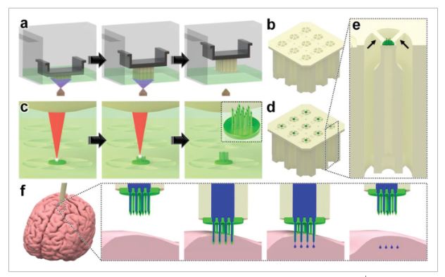
Conceptual illustrations of the hybrid additive manufacturing strategy for 3D microprinting hollow, high-aspect-ratio microneedle arrays (MNAs) for microinjection applications. a,b) Digital light processing (DLP)-based 3D printing of batch capillaries. a) A liquid-phase photocurable material is UV-crosslinked in designated locations in a layer-by-layer manner to produce a batch of arrayed capillaries comprising cured photomaterial. b) The DLP-printed batch of prealigned capillaries following the development process. c–e) “Ex situ direct laser writing (esDLW)” of MNAs directly atop—and fluidically sealed to—each DLP-printed capillary. c) A femtosecond pulsed IR laser is scanned to selectively initiate two-photon polymerization of a liquid-phase photocurable material in a point-by-point, layer-by-layer manner to produce MNAs comprising cured photomaterial. d) A batch array of MNA-capillary assemblies following the DLW-associated development process. e) Individual MNA-capillary assemblies within the array can be released on demand by manually severing the supporting structures (arrows). f) Example application of integrating MNA-capillary assemblies with nanoinjector systems to facilitate MNA-mediated simultaneous, distributed microinjections of target fluidic substances/suspensions into brain tissue.
2 Results and Discussion
Hybrid Additive Manufacturing of Hollow MNAs
The presented hybrid additive manufacturing strategy consists of two fundamental stages: i) DLP 3D printing of batch arrays of capillaries and ii) esDLW-based printing of the MNAs directly atop each capillary. DLP 3D printing is a vat photopolymerization approach in which a DLP projector is used to UV-crosslink a liquid-phase photocurable material in designated locations in a layer-by-layer manner to ultimately produce 3D objects composed of cured photomaterial.[62] Here, we leveraged DLP 3D printing to fabricate batches of arrayed capillaries in a single print run to overcome several drawbacks of recent esDLW approaches for printing 3D micro/nanostructured objects onto mesoscale fluidic components, such as micropiston-based microgrippers[63] and liquid biopsy systems[64] onto fluidic capillaries. First, the geometric control afforded by DLP 3D printing allows for each capillary to be designed with a variable OD to match the dimensions of the capillary base to those of the desired injector system. This capillary-specific geometric customization capability obviates the need for additional fluidic adapters and/or sealants (e.g., glues) often required to couple the mesoscale capillaries to macroscale fluidic equipment (e.g., injector systems).[63-65] Second, the outer dimensions of the batch array can be designed to support facile loading into the DLW 3D printer, which eliminates the time, labor, and costs associated with manufacturing and employing custom-built capillary holders typically needed for esDLW approaches.[63-65] Lastly, the ability to print all of the capillaries in predefined array locations—with uniform surface positions and rotational orientations—addresses critical deficits associated with the use of custom-built capillary holders that rely on undesired manual (e.g., by hand and/or eye) alignment protocols for each individual capillary.[65]
For DLP 3D printing of the batch capillary arrays, we used a Miicraft M50 microfluidics DLP 3D printer (CADworks3D, Toronto, ON, Canada) to fabricate two batches (i.e., 18 capillaries in total) per print run, which corresponded to a total print time of less than 45 min (Movie S1, Supporting Information). To enable direct integration with the nanoinjector system (MO-10, Narishige International USA, Inc., Amityville, NY), we designed each capillary with a consistent inner diameter (ID) of 650 µm, but with a variable OD that was set at 1.2 mm for the top 1.5 mm and then gradually increased to 2.4 mm for the remainder of the 10 mm length of the capillary (Figure S1, Supporting Information). Fabrication results revealed effective construction of the arrayed capillaries—each attached to the batch via five connecting structures (400 µm in width and depth; 1.5 mm in length) (Figure 2a,b). In addition, the outer dimensions of the overall batch resolved such that the print could be readily loaded into the multi-DiLL holder of the DLW system (Photonic Professional GT2, Nanoscribe GmbH, Germany) (Figure S2, Supporting Information) to facilitate esDLW-based 3D printing.
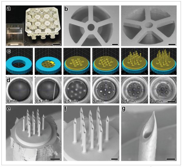
Fabrication results for DLP 3D printing of batch arrays of capillaries and esDLW-based printing of MNAs. a,b) DLP prints of batch arrays of capillaries. a) Photograph of a complete batch with nine arrayed capillaries. Scale bar = 5 mm. Inset shows two batches attached to the build plate directly after DLP 3D printing (see Movie S1 in the Supporting Information). b) Low-vacuum scanning electron microscopy (SEM) images of a representative DLP-printed capillary attached to the batch via five connecting structures. Scale bars = 500 µm. c,d) The esDLW approach for printing MNAs directly onto DLP-printed capillaries in a single print run. c) Computer-aided manufacturing (CAM) simulations and d) corresponding images of the esDLW printing process. Scale bar = 250 µm (see Movie 2 in the Supporting Information). e–g) Low-vacuum SEM images of representative fabrication results showing: e) an esDLW-printed MNA atop a DLP-printed capillary following release from the batch array (see Movie S3 in the Supporting Information); f) a magnified view of the MNA; and g) a magnified view of a single microneedle tip in the array. Scale bars = e) 250 µm, f) 100 µm, and g) 25 µm.
We designed the MNAs to include identical hollow microneedles—each with an ID of 30 µm, an OD of 50 µm, and a height of 550 µm—with needle-to-needle spacing of 100 µm (Figure S3, Supporting Information). For the esDLW printing process, we initiated the print with 50 µm of overlap with the top surface of the capillary to ensure bonding at the interface. Computer-aided manufacturing (CAM) simulations and brightfield images of a corresponding esDLW process for printing the MNA directly onto a DLP-printed capillary are presented in Figure 2c,d, respectively (see also Movie S2, Supporting Information). The total esDLW printing process was completed in ≈10 min. Following development, we retrieved target MNA-capillary assemblies from the batch by manually severing the five connecting structures (Movie S3, Supporting Information). Images of the released MNA-capillary assemblies captured using low-vacuum scanning electron microscopy (SEM) revealed effective alignment and integration of the esDLW-printed MNAs with the DLP-printed capillaries, without any visible signs of physical defects along the MNA-capillary interface (Figure 2e). In addition, images of the esDLW-printed MNA and needle tips suggest that the manual release process did not appear to affect MNA integrity (Figure 2f,g).
In Silico and In Vitro Investigations of MNA Mechanical Performance
The critical first steps of MNA-based microinjection protocols involve the effective puncture and penetration into a target medium (e.g., biological tissue), which can impart significant mechanical forces on the microneedles.[66] Thus, the potential utility of MNAs is predicated on their ability to successfully withstand such mechanical loading conditions. To evaluate this capability for the esDLW-printed high-aspect-ratio MNAs, we employed both numerical and experimental approaches to elucidate the mechanical performance of the MNAs. We performed finite element analyses (FEA) to provide insight into the mechanical failure behavior of the MNAs when subjected to a compressive load applied longitudinally with respect to the needles. The simulation results revealed that each arrayed microneedle exhibited a buckling-like deformation with the largest displacements observed around the midpoint of the heights; however, needles positioned in the outer region (i.e., the needles radially arrayed farthest from the center of the MNA) displayed larger deformations compared to those located in the more central array positions (Figure 3a). This behavior arises from the load distribution caused by the disc-like base of the MNA, which deforms more in its central region than its peripherical region, thereby allowing the centrally located microneedles to rigidly displace more in the axial direction than their outer-region counterparts. According to the stress–strain curve generated from the FEA compressive loading simulations (Figure 3b), the overall MNA exhibited an effective Young's Modulus (E) of 4.31 MPa and yield strength (σy) of 135 kPa. We also numerically modeled MNA mechanics associated with puncture into the brain tissue. By characterizing the nonlinear response at the interface between the tips of the microneedles and the brain substrate, we found that the forces associated with the needles located in the outer region were larger than those in the central regions (Figure S4, Supporting Information), which is in agreement with the compressive loading analyses (Figure 3a).
The critical first steps of MNA-based microinjection protocols involve the effective puncture and penetration into a target medium (e.g., biological tissue), which can impart significant mechanical forces on the microneedles.[66] Thus, the potential utility of MNAs is predicated on their ability to successfully withstand such mechanical loading conditions. To evaluate this capability for the esDLW-printed high-aspect-ratio MNAs, we employed both numerical and experimental approaches to elucidate the mechanical performance of the MNAs. We performed finite element analyses (FEA) to provide insight into the mechanical failure behavior of the MNAs when subjected to a compressive load applied longitudinally with respect to the needles. The simulation results revealed that each arrayed microneedle exhibited a buckling-like deformation with the largest displacements observed around the midpoint of the heights; however, needles positioned in the outer region (i.e., the needles radially arrayed farthest from the center of the MNA) displayed larger deformations compared to those located in the more central array positions (Figure 3a). This behavior arises from the load distribution caused by the disc-like base of the MNA, which deforms more in its central region than its peripherical region, thereby allowing the centrally located microneedles to rigidly displace more in the axial direction than their outer-region counterparts. According to the stress–strain curve generated from the FEA compressive loading simulations (Figure 3b), the overall MNA exhibited an effective Young's Modulus (E) of 4.31 MPa and yield strength (σy) of 135 kPa. We also numerically modeled MNA mechanics associated with puncture into the brain tissue. By characterizing the nonlinear response at the interface between the tips of the microneedles and the brain substrate, we found that the forces associated with the needles located in the outer region were larger than those in the central regions (Figure S4, Supporting Information), which is in agreement with the compressive loading analyses (Figure 3a).
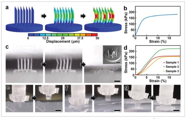
Numerical and experimental results for MNA mechanical characterizations. a,b) Finite element analysis (FEA) results for a) microneedle deformations and b) stress–strain curve corresponding to MNA mechanics under compressive loading conditions. c,d) Experimental results for MNA compression testing. c) Sequential images of the MNA during axial compression test. Inset shows an SEM image of an MNA following compressive failure. Scale bars = 250 µm (see Movie S4 in the Supporting Information). d) Stress–strain curve generated from compressive loading experiments (n = 3 MNAs). e–g) Sequential images of representative MNA penetration and retraction operations corresponding to hydrogels with agarose concentrations of: e) 2.4%, f) 5%, and g) 10%. Scale bars = 500 µm (see Movie S5 in the Supporting Information).
To experimentally examine the mechanical performance of the esDLW-printed MNA, we conducted two sets of puncture and penetration-associated studies. First, we performed axial compression tests with esDLW-printed MNAs (n = 3), which revealed buckling-type deformations of the microneedles with increasing loading until complete mechanical failure (Figure 3c and Movie S4, Supporting Information). From SEM images of MNAs following compressive testing, we observed several cases of complete fracture, but the majority of the arrayed microneedles remained intact with the caveat that the tips and the overall shapes of the needles exhibited plastic deformation (Figure 3c, inset). Quantified results for the stress–strain relationships for the esDLW-printed MNAs revealed an average E of 2.12 ± 0.35 MPa and σy of 155 ± 30 kPa (Figure 3d). Although these results provide insight into the upper boundaries of mechanical loading, compression testing using an impenetrable plate is limited in its direct relevance to microinjection applications that rely on microneedle penetration into a target medium. Thus, we also investigated the capacity for the esDLW-printed MNAs to puncture and penetrate into surrogate hydrogels with increasing concentrations of agarose that correspond to varying degrees of biologically relevant stiffness. In particular, we performed experiments with agarose concentrations of: i) 1.2% (E = 12.8 ± 1.1 kPa), which would support penetration into liver and breast tissue; ii) 2.4% (E = 27.5 ± 1.0 kPa), which is relevant to brain, heart, kidney, arterial, and prostate tissue; and iii) both 5% (E = 223 ± 14 kPa) and 10% (E = 268 ± 31 kPa), which are relevant to cartilage tissues (Figure S5, Supporting Information).[67-70] Experimental results revealed that the MNA successfully penetrated into the 1.2%, 2.4%, and 5% agarose gels; however, we observed buckling of the microneedles and failure to penetrate into the 10% agarose gel (Figure 3e–g and Movie S5, Supporting Information). These results suggest that the esDLW-printed MNA is sufficient for penetration into brain tissue as well as a variety of other tissues (e.g., liver, breast, heart, kidney, arterial, and prostate tissues), but alternative photomaterials (with stronger mechanical properties) and/or microneedles with geometrically enhanced strength (e.g., by increasing the OD) would be needed for microinjection applications involving target mediums with E in excess of 250 kPa.
In Vitro Microfluidic Interrogations of MNA-Capillary Interface Integrity
One of the most catastrophic failure modes for esDLW-based prints—whether for optical,[71] photonic,[72] mechanical,[73] or fluidic[63-65] structures—is the potential for the DLW-printed objects to detach from the meso/macroscale components on which they are additively manufactured. For biomedical MNA applications, the consequences of this type of failure could be particularly serious, such as an MNA detaching from the capillary while embedded in brain tissue following microinjection. To investigate the potential for this failure mode and, in turn, provide insight into the mechanofluidic integrity of the interface between the esDLW-printed MNAs and the DLP-printed capillaries, we performed microfluidic cyclic burst-pressure tests with the MNA-capillary assemblies. Initially, using an applied pressure set at 5 kPa, we gradually infused blue-dyed deionized (DI) water into the MNA-capillary assembly via the opposing end of the capillary (i.e., the side without the printed MNA) until the fluid began exiting the tips of the arrayed microneedles (Figure 4a and Movie S6, Supporting Information). Thereafter, we performed separate sets of cyclic burst-pressure experiments (n = 100 cycles per experiment) corresponding to applied pressures set at 100, 200, and 300 kPa (Figure 4b–d). Throughout the burst-pressure testing, we monitored the MNA-capillary interface under brightfield microscopy for visible signs of undesired leakage phenomena (e.g., fluid exiting at any point along the interface rather than out of the tops of the microneedle tips); however, we did not observe any instances of such flow behavior. Similarly, quantified results of fluid flow through the MNA-capillary assembly recorded during the burst-pressure tests did not exhibit any indications of burst events—i.e., large increases in flow rates after a certain point, despite the applied pressure remaining constant—nor signs of gradual leakage phenomena associated with the flow rates increasing from pressure cycle to pressure cycle over the course of the experiment. Rather, the flow rate magnitudes corresponding to the applied input pressures remained consistent throughout the burst-pressure experiments (Figure 4b–d), suggesting uncompromised fluidic integrity of the MNA-capillary interface for all cases examined.
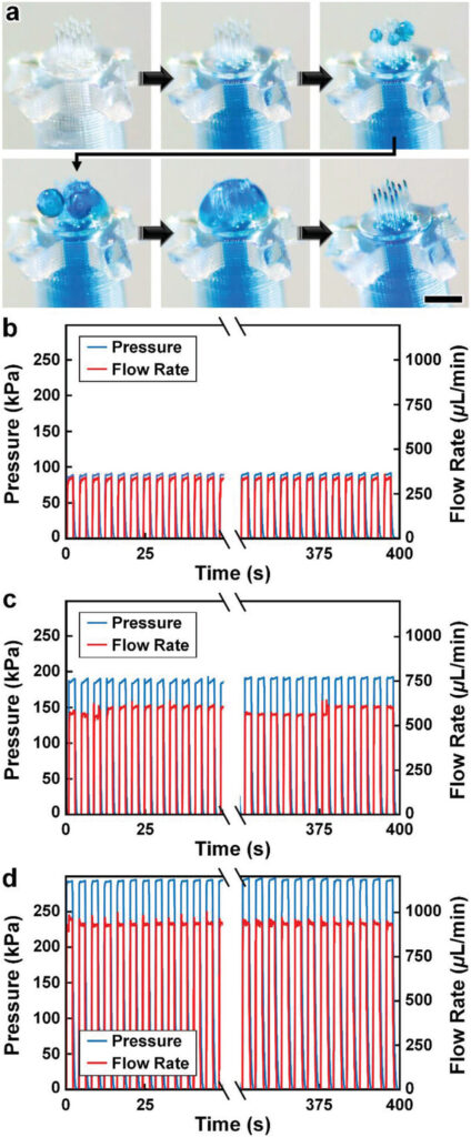
Experimental results for MNA microfluidic investigations. a) Sequential images during fluidic infusion. Scale bar = 500 µm (see Movie S6 in the Supporting Information). b–d) Quantified results for representative cyclic burst-pressure experiments (n = 100 cycles) corresponding to input pressures targeting: b) 100 kPa, c) 200 kPa, and d) 300 kPa.
Ex Vivo Mouse Brain Studies of MNA Penetration, Microinjection, and Retraction Functionalities
As an exemplar with which to interrogate the penetration, microinjection, and retraction capabilities of the esDLW-printed MNAs, we excised brains with intact dura mater from euthanized 6-month-old male mice (Wildtype C57BL/6 J, Jackson Laboratory) for experimentation ex vivo (Figure 5a). We performed three sets of experiments to elucidate these fundamental MNA functionalities. First, we investigated the ability to execute penetration and retraction operations (but not fluidic microinjections) with the MNAs as critical measures of performance with respect to three potential failure modes that would critically limit the efficacy of the esDLW-printed MNAs: i) the sharpness of the tips of the microneedles—governed by the resolution of the DLW 3D printer—is insufficient to puncture the brain tissue without inducing significant deformation of the brain; ii) the mechanical properties of the high-aspect-ratio microneedles lead to buckling and/or fracture of the microneedles prior to effective penetration into the brain tissue; and/or iii) the forces during the penetration or retraction processes fracture the microneedles, causing microneedles (or fragments of microneedles) to remain embedded in the brain tissue after retraction completion. To facilitate the penetration and retraction studies, we interfaced each MNA-capillary assembly examined with a nanoinjector system fixed to a stereotactic frame as a means to enable precise position control while optically monitoring the MNA-brain tissue interactions. Experiments performed with three distinct MNA-capillary assemblies (n = 3 penetration and retraction operations for each distinct MNA-capillary assembly) revealed that the MNAs could successfully puncture the brain tissue within 1 mm of total displacement from initial contact and, importantly, without any visible signs of mechanical failure during any of the penetration or retraction operations (Figure 5b and Movie S7, Supporting Information). Images of the MNAs (captured after completion of the retraction process) corroborated these results, without any indications of microneedle-associated failure modes (e.g., buckling or fracture) or MNA detachment from the capillary (Figure 5c).
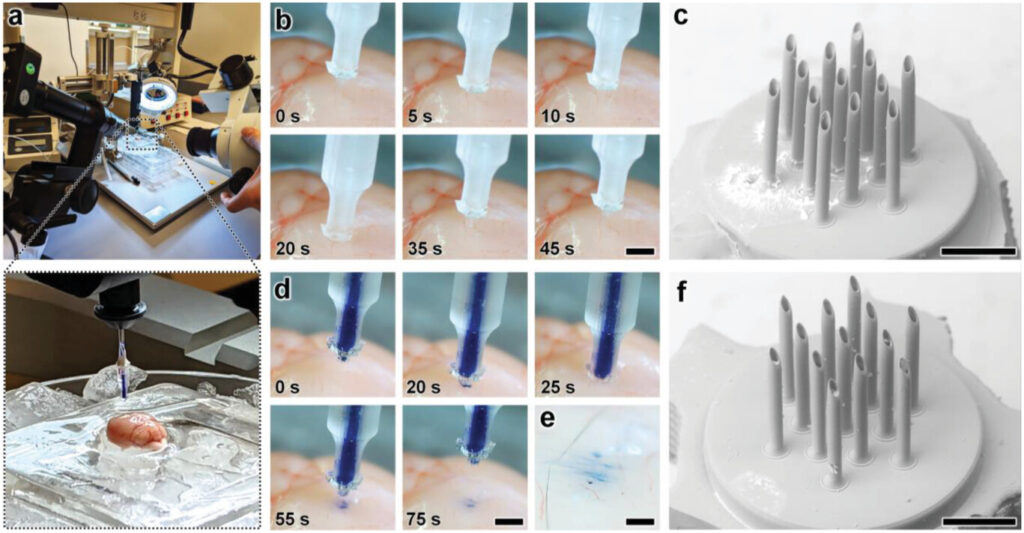
Experimental results for ex vivo MNA penetration, microinjection, and retraction operations using an excised mouse brain. a) Experimental setup including the MNA-capillary assembly interfaced with a custom-built nanoinjector and an excised mouse brain on ice. b,c) Brain tissue puncture and retraction results. b) Sequential images of MNA insertion into (≤20 s) and retraction from (≥20 s) the brain tissue. Scale bar = 1 mm (see Movie S7 in the Supporting Information). c) SEM image of the MNA after retraction from the brain tissue. Scale bar = 250 µm. d–f) MNA-mediated microinjection results. d) Sequential images of a representative MNA penetration, microinjection, and retraction process for a surrogate fluid (blue-dyed DI water) injected into brain tissue. Scale bar = 1 mm (see Movie S8, Supporting Information). e) Magnified view of the postinjection site. Scale bar = 250 µm. f) SEM image of the MNA following microinjection into the brain tissue. Scale bar = 250 µm.
After validating the penetration and retraction capabilities, we then initially investigated the microinjection functionality of the MNAs based on the ability to deliver a surrogate microfluidic payload into the brain tissue. In this case, we preloaded the MNA-capillary assembly with blue-dyed (1.5% Evan's Blue) DI water, and then interfaced the assembly with the nanoinjector (Figure 5a, expanded view) for control of both the MNA position and fluidic microinjection dynamics. Although the results for the cyclic microfluidic burst-pressure experiments performed in vitro (Figure 4b–d) suggested that the MNA-capillary interface should withstand the forces associated with microinjections into the brain tissue, we optically monitored the overall MNA-capillary assembly during the microinjection process for potential signs of undesired leakage via the interface. Akin to the tissue penetration and retraction studies, we used the stereotaxic frame to guide the descent of the MNA into the brain tissue (Figure 5d, top and Movie S8, Supporting Information). Following completion of the penetration process, we then used the pneumatically controlled nanoinjector to dispense the surrogate dyed fluid through the MNA-capillary assembly and, in turn, deliver the fluid into the brain tissue. Thereafter, we retracted the MNA from the brain (Figure 5d, bottom and Movie S8, Supporting Information), and then washed the surface of the injection site with phosphate buffered saline (PBS) to eliminate any residual surrogate fluid from the surface, such that the only remaining fluid was located beneath the tissue surface (Figure 5e). Throughout the microinjection process, we did not observe any undesired leakage phenomena (Movie S8, Supporting Information), with optical characterizations of the postinjection site indicating effective, distributed MNA-mediated delivery of the surrogate fluid well below the surface of the excised brain (Figure 5e). Furthermore, SEM images of the MNA-capillary assembly following tissue penetration, fluidic microinjection, and retraction revealed uncompromised structural integrity (Figure 5f).
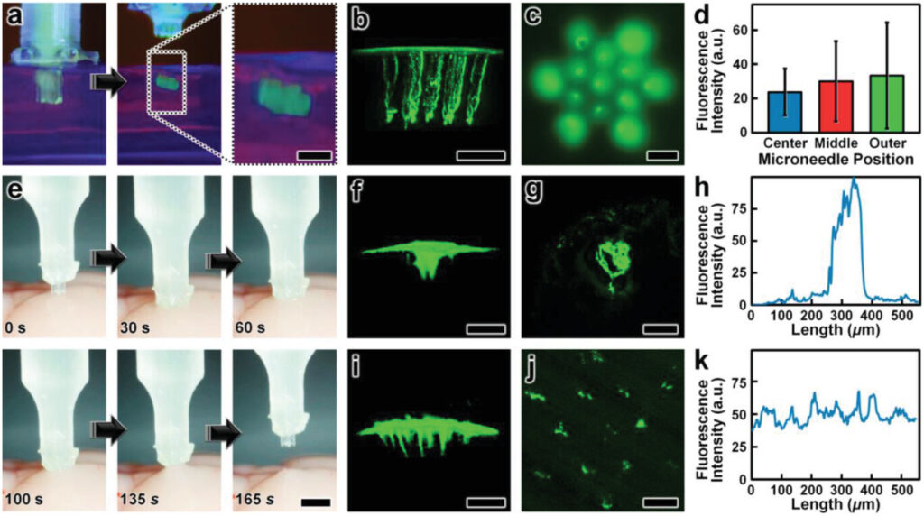
Lastly, we evaluated the microinjection performance of the esDLW-printed MNA compared to a conventional needle (Hamilton 33G) widely used for delivering therapeutics into brain tissue.[74] In this case, we used a suspension of fluorescently labeled nanoparticles (100 nm in diameter) as the surrogate microfluidic payload. As an initial positive experimental control for the esDLW-printed MNA, we performed microinjections (n = 3 MNAs) of the nanoparticle suspension into 0.6% agarose gel in vitro (Figure 6a and Movie S9, Supporting Information) and visualized the particle distributions using two-photon (Figure 6b S10) and widefield fluorescence microscopy (Figure 6c). We observed injected nanoparticles corresponding to each microneedle in the array—which included one microneedle in the center of the array, six needles arrayed radially in a middle region (150 µm from the center), and six needles arrayed radially in an outer region (260 µm from the center)—but to determine if microneedle array position influenced injection behavior, we analyzed the fluorescence intensities associated with each arrayed needle. Quantified results revealed that the fluorescence intensities were statistically indistinguishable, with no discernable difference for the microneedle injection sites between the center and either the middle (p = 0.66) or outer regions (p = 0.61), nor between the middle and outer regions (p = 0.72) (Figure 6d). Thereafter, we performed microinjections of the nanoparticle suspension into excised mouse brains using both the conventional needle and the esDLW-printed MNA (Figure 6e and Movie S10, Supporting Information). Two-photon fluorescence images of the injection sites revealed stark differences in the nanoparticle distributions associated with each needle system. In the conventional needle case, the nanoparticles accumulated tightly within the single needle track (Figure 6f,g). For example, quantified fluorescence intensity results revealed that the majority of the fluorescence signal was detected within an ≈150 µm region (Figure 6h). In contrast, MNA-associated microinjection sites exhibited a more homogeneous distribution of injected nanoparticles over a larger area (Figure 6i,j)—with particles detected at sites corresponding to each arrayed microneedle—resulting in a more consistent fluorescence signal along the length of the injection site (Figure 6k). These results suggest that MNAs offer an effective means to distribute fluidic payloads more uniformly over a larger area compared to conventional single-needle systems. In combination, these experimental results for MNA penetration, surrogate fluid/suspension delivery, and retraction functionalities using an ex vivo mouse brain provide an important foundation for the utility of the presented hybrid DLP-DLW-enabled MNAs for microinjection applications.
