3D Printing of Inertial Microfuidic Devices
Sajad Razavi Bazaz, Omid Rouhi, MohammadAmin Raouf, Fatemeh Ejeian, MohsenAsadnia, Dayong Jin and Majid Ebrahimi Warkiani
Inertial microfluidics has been broadly investigated, resulting in the development of various applications, mainly for particle or cell separation. Lateral migrations of these particles within a microchannel strictly depend on the channel design and its cross-section. Nonetheless, the fabrication of these microchannels is a continuous challenging issue for the microfluidic community, where the most studied channel cross-sections are limited to only rectangular and more recently trapezoidal microchannels. As a result, a huge amount of potential remains intact for other geometries with cross-sections difficult to fabricate with standard microfabrication techniques. In this study, by leveraging on benefits of additive manufacturing, we have proposed a new method for the fabrication of inertial microfluidic devices. In our proposed workflow, parts are first printed via a high-resolution DLP/SLA 3D printer and then bonded to a transparent PMMA sheet using a double-coated pressure-sensitive adhesive tape. Using this method, we have fabricated and tested a plethora of existing inertial microfluidic devices, whether in a single or multiplexed manner, such as straight, spiral, serpentine, curvilinear, and contraction-expansion arrays. Our characterizations using both particles and cells revealed that the produced chips could withstand a pressure up to 150 psi with minimum interference of the tape to the total functionality of the device and viability of cells. As a showcase of the versatility of our method, we have proposed a new spiral microchannel with right-angled triangular cross-section which is technically impossible to fabricate using the standard lithography. We are of the opinion that the method proposed in this study will open the door for more complex geometries with the bespoke passive internal flow. Furthermore, the proposed fabrication workflow can be adopted at the production level, enabling large-scale manufacturing of inertial microfluidic devices.
We kindly thank the researchers at University of Technology Sydney for this collaboration, and for sharing the results obtained with their system.

Introduction
Inertial microfuidics has been broadly investigated, resulting in the development of various applications, mainly for particle or cell separation. Lateral migrations of these particles within a microchannel strictly depend on the channel design and its cross-section. Nonetheless, the fabrication of these microchannels is a continuous challenging issue for the microfuidic community, where the most studied channel cross-sections are limited to only rectangular and more recently trapezoidal microchannels. As a result, a huge amount of potential remains intact for other geometries with crosssections difcult to fabricate with standard microfabrication techniques. In this study, by leveraging on benefts of additive manufacturing, we have proposed a new method for the fabrication of inertial microfuidic devices. In our proposed workfow, parts are frst printed via a high-resolution DLP/SLA 3D printer and then bonded to a transparent PMMA sheet using a double-coated pressure-sensitive adhesive tape. Using this method, we have fabricated and tested a plethora of existing inertial microfuidic devices, whether in a single or multiplexed manner, such as straight, spiral, serpentine, curvilinear, and contraction-expansion arrays. Our characterizations using both particles and cells revealed that the produced chips could withstand a pressure up to 150psi with minimum interference of the tape to the total functionality of the device and viability of cells. As a showcase of the versatility of our method, we have proposed a new spiral microchannel with right-angled triangular cross-section which is technically impossible to fabricate using the standard lithography. We are of the opinion that the method proposed in this study will open the door for more complex geometries with the bespoke passive internal fow. Furthermore, the proposed fabrication workfow can be adopted at the production level, enabling large-scale manufacturing of inertial microfuidic devices.
Continuous separation of particles and cells is required for a wide variety of applications that include mineral processing, chemical syntheses, environmental assessments, and biological assays1 . A number of conventional methods exist for this purpose; however, they have several drawbacks. Membrane fltration-based techniques, while effici t and simple, are limited by flter fouling and clogging. Centrifugation methods are also plagued by problems of particle adhesion and clogging, along with their high cost and inability for continuous processing. Likewise, techniques based on sedimentation are prone to particle adhesion and slower processing time, which increases the non-viability of cells in biological applications. Also, methods based on magnetic-activated cell sorting (MACS) and fuorescence-activated cell sorting (FACS) are proven to be low throughput and expensive2–4 . With the evolution of microfabrication and rapid prototyping techniques, microfluidic technology has emerged as an alternative to improve upon conventional separation techniques5,6 . Tese microfuidic techniques are grounded on the unique characteristics of microscale fl w phenomena and have recently gained prominence as effici t tools for the control and focusing of microbeads. Amongst existing microfuidic systems, inertial microfuidics has experienced massive growth in many applications ranging from cell separation7,8 , cytometry9,10, multiplexed bio-assays11,12, and also fuid mixing13. Despite great advantages of inertial microfuidics, the commercial impact and scalability of this technology have been restricted due to fabrication issues. As a passive technique, inertial microfuidic systems manipulate cells and particles by taking the advantage of hydrodynamic forces in microchannels with a variety of cross-sections. To date, several microchannels (i.e.,straight, spiral, and serpentine) with diferent cross-sections (i.e., square, rectangular, triangular, trapezoidal, and circular) have been proposed to enhance particle sorting by optimizing the synergetic efects of inertial and Dean drag forces14–18. Tese devices are mainly fabricated by casting PDMS on a master mold, which is made by either standard microfabrication techniques (i.e., silicon etching or SU8 lithography) or using conventional micromilling on an aluminum or polymethylmethacrylate (PMMA) sheets19–21. While this approach has been the workhorse behind the development of majority of these devices, the inability to build non-orthogonal and non-planar structures, cost, and labor intensiveness of the process have hampered its widespread applications and commercialization22,23.
Besides the aforementioned approach, other groups attempted to develop alternative strategies for the fabrication of inertial microfuidic devices. For instance, several groups reported the usage of femtosecond laser irradiation and CO2 laser ablation techniques to produce straight and spiral shape microchannels inside a glass or PMMA24–28. Despite the simple fabrication process, the complexity of building non-rectangular cross-sections, poor surface fin sh, and lengthy etching steps are making them less user-friendly. Some groups also proposed the utilization of metal micro-wires or a sacrific al template in conjunction with soflithography to produce inertial microfuidic devices29–31. In spite of the simplicity of this method in the fabrication of circular channels, PDMS rupture or distortion and the presence of residuals in microchannels during the template removal restrict its utility.
Recently, the fabrication of PMMA microchannels using hot embossing technique has also been reported. While this method is attractive for rapid prototyping and high volume production of microfuidic systems with microscale features, the necessity of using sophisticated equipment limits its widespread usage32,33. Recently, additive manufacturing has emerged as a powerful platform to fabricate 3D functional microfuidic systems from a variety of polymeric materials34. Th s outstanding technology enables investigators to build microstructures with complex shapes and geometries in a short time35,36. Benefting from the stereolithography apparatus (SLA) technique37, Lee et al. directly fabricated a 3D helical trapezoidal microchannel to separate E. coli bacteria using magnetic nanoparticle clusters38. However, due to the poor transparency of the fabricated channel, imaging (whether fuorescent or bright fi ld) was not feasible through the channel. Besides, to remove residuals from channels, the channel width is in the order of millimeter-sized dimensions, which is not suitable for most of the inertial microfuidic applications where small cells or particles are of interest. More lately, 3D printing of sacrific al molds combined with soflithography has gained signifi ant attention due to its simplicity and cost-efectiveness39. Gaining the effici cy of the fused deposition modeling (FDM) printer, Tang and colleagues40 fabricated various microchannels with unconventional cross-sections to study the efect of geometry on elasto-inertial focusing. While this approach is suitable to fabricate microchannels with diferent cross-sections, the resolution of printed parts is not high enough due to inherent limitations of FDM printing. Although direct fabrication of microchannels using SLA and digital light processing (DLP) method is a suitable candidate, inertial microfuidic devices ofen operate in channels in the order of micrometer (e.g., rectangular with 200 µm width and 40µm height) where removing resin residuals from the channel is a challenging issue41.
To address these inadequacies, we have developed a robust protocol for large-scale manufacturing of inertial microfuidic systems. Tanks to the capabilities of DLP and SLA 3D printing42,43, we have printed a wide range of microchannels with diferent geometries, capable of performing particle and cell focusing for various Reynolds numbers (Re). Te approach makes the use of a double-coated pressure-sensitive adhesive tape that perfectly binds open 3D-printed microchannels with optically transparent acrylic sheets, producing a leakage-free interface for inertial microfuidic applications. Te bonding strength is quantifi d, and the compatibility of the concept for the fabrication of new generation of inertial microfuidic devices is evaluated using cells and particles.

Results and discussion
Fabrication and characterization of 3D-printed channels.
Soflithography using PDMS and a master mold is a frequently used method for the fabrication of microfuidic systems. Th s strategy has several advantages; for instance, PDMS is biocompatible, optically transparent, and gas permeable, which makes it suitable for a myriad of biological applications44. Also, 3D printing of PDMS has been reported using stereolithography approach45. However, certain drawbacks such as lack of chemical stability, deformation under pressure, and adsorption of small hydrophobic molecules have hindered its industrial-scale utilization. Moreover, the manual molding, cleaning, and bonding process complicate the mass production.
Although theoretically straightforward, scaling up of PDMS-made microchannels for commercialization application in inertial fl ws is challenging since these devices are flex ble and prone to rupture or collapse at high fl w rates. In addition, infation and hysteresis feature of PDMS create a big question mark regarding the exact focusing position of particles. Tis becomes more serious in CFD modeling where the “fxed wall boundary condition” is not truly correct in inertial regimes within PDMS-made microchannels. It is not surprising that the results of numerical simulations must be validated with hard chips rather than soft (PDMS-made) microchannels. Apart from these issues, the inherent limitations in the standard microfabrication and soflithography techniquesmake researchers unable to explore particle migration in unconventional cross-sections (e.g., right-angled triangular or hexagonal). For instance, particle focusing within a triangular curved microchannel has never been explored due to the fabrication difculty. As such, there is a great need to develop standardized protocols for the fabrication of inertial microfuidic devices to facilitate ground-breaking research, while enabling quick translation into commercial products.
In this study, we have proposed a novel approach for the fabrication of inertial microfuidic devices based on the 3D printing method. Figure 1 demonstrates an overview of the fabrication process. Gaining the effici cy of a high-resolution 3D printer, the desired microchannel is printed while its face (where the design pattern exists) is outer, and the base is attached to the build plate (Fig. 1AI). Th s method is particularly signifi ant since the change of cross-sections in inertial microfuidics is of great interest. However, the printing parameters need to be optimized for the fabrication of a channel with proper and accurate dimensions. Te slice thickness
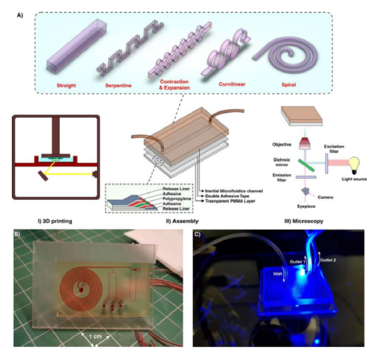
Figure 1. (A) Schematic illustration of the proposed workfl w for the fabrication of inertial microfuidic devices. I. Te desired channel geometry was printed by a high-resolution SLA/DLP 3D printer II. Afer cleaning the part by isopropanol, it was bonded to a PMMA sheet by means of a double-coated pressuresensitive adhesive tape. Te entire process just takes less than two hours. III. Beneftting from the PMMA transparency, high-speed, fuorescent, bright fi ld, or phase contrast microscopy can be performed from the bottom side of the channel (B) An actual complicated inertial microfuidic device containing a spiral and serpentine microchannel. (C) Fluorescent microscopy from the bottom side of the channel.
in Z direction, curing time of each layer, and total thickness of the part are the most critical factors to have a high-quality channel with a great surface fin sh. Various cross-sections, ranging from right-angled or isosceles triangular to hexagonal, were fabricated and the best optimized parameters were identifi d (Fig. S1). To complete the fuidic network, 3D-printed inertial microchannels need to be bonded to a substrate with enough optical transparency and rigidity for subsequent testing. In this work, a variety of scenarios has been evaluated, and upon extensive evaluations and characterizations, permanent bonding of 3D-printed channels to a PMMA sheet via a double-coated adhesive tape was selected as the most promising and reproducible method. A transparent double-coated pressure-sensitive adhesive tape (ARcare, Adhesive Research) having 25.4 µm clear polyester flm coated with AS-110 acrylic medical grade adhesive was cut with a similar size of PMMA sheet (Fig. 1AII). Afer the attachment of one side of the tape to the PMMA sheet, the 3D-printed inertial part was manually placed over the other side of the tape and pressed with a tweezer until no bubble was observed at the interface (Fig. S2).
An important feature of PDMS is its optical transparency, which makes it suitable for a broad range of microscopic applications. Given the fact that commercial DLP/SLA resins are not typically transparent, the attachment of 3D-printed microchannels to PMMA sheets provides enough transparency for the optical and fuorescent microscopy (Fig. 1AIII). What makes this approach attractive for a wide range of communities (e.g., biologists and chemists) is its user-friendliness for people without prior knowledge about microfabrication and soflithography. Te entire process from CAD drawing to printing and then testing takes less than 2 hours, portraying the versatility of this method for inertial microfuidic research. More importantly, devices made using this technique are not prone to the deformation and leakage compared to the PDMS-made devices, making them suitable to study new physics, especially at high Re. Furthermore, by considering the fabrication cost, time, and efforts of a complicated inertial microfuidic device, our suggested method is rapid and utilizes a low-cost raw material which are valuable features, especially in areas where resources are limited. Figure 1B,C depict a fi al device fabricated using this technique. Te internal channels are flled with red food color for the sake of illustration.
In order to investigate the bonding quality, a straight microchannel with dimensions of 50 µm height, 200 µm width, and 4 cm length was fabricated and tested accordingly. We have monitored the device performance for the appearance and growth of Safman-Taylor fi gers until it becomes stable, called “infation stability” (Fig. 2A). Te results are presented in a 2D diagram to identify the channel behavior at a given pressure, as shown in Fig. 2C. Our results revealed that the holding strength of double-coated adhesive tape was able to achieve a leak-proof interface between the 3D-printed part and PMMA sheet, not only at typical operating pressure reported in literature46, but also more than the capability of PDMS-made channels in withstanding high fl w rate conditions. Shear rate distribution across a line parallel to the channel width was also evaluated, and as Fig. 2B revealed, increasing the fl w rate leads to imposing more shear forces at the edges of the channels. Te more the fl w rate, the larger the appearance of Safman-Taylor fi gers (insets of Fig. 2B). Te green area in Fig. 2C shows the safe zone for performing inertial microfuidic experiments where no Safman-Taylor fi gers appear during the operation. We have found that at pressures more than 82.6 psi, Safman-Taylor fi - gers begin to appear; however, this does not impose any detrimental efect on the device performance (i.e., no leakage or bonding collapse). Also, we did not observe any delamination or deformation in channels afer consecutive runs at high pressures (i.e., 120 psi), all of which are common in PDMS-based inertial microfuidic devices (see Figs. S3 and S4 for the pressure drop, velocity profle inside the microchannels for a wide range of operating fl w rates).
The surface characteristic of the double-coated adhesive tape was also investigated using a proflometer. As Fig. 3 illustrates, the roughness of the tape is homogenous and is in the submicron range. Te values of Ra and Sa were about 250 and 240nm, respectively. Also, the roughness of the 3D printed parts was evaluated and value of Sa was less than 300 nm. Tese nanometric rugosities indicate that the roughness of tape does not have any efect on the fow profle and particle focusing. Although optically transparent, the optical characteristics of the PMMA sheet (2-mm-thick) and adhesive tape were evaluated to identify the possibility of accurate fuorescence imaging47. Hence, the UV-visible absorbance spectra for a wide range of wavelengths (i.e., from 200 to 1100nm) were recorded via a spectrophotometer (Cary 60 VU-Vis spectrophotometer, Agilent Technologies). Figure 3B,C reveal that the light loss is negligible for both PMMA and adhesive tape within the visible spectrum, resulting in no trace of autofuorescence residual.
Straight microchannel.
Straight microchannels with rectangular or square cross-sections are arguably the most widely used inertial microfuidic systems. Tanks to their ease of fabrication and the ability for parallelization, a myriad of applications have been developed using these platforms over the past decade48. Te required channel length for inertial particle migration to the equilibrium positions is L H = πμ /ρ α U f f m L 2 2 where fL is estimated in the range of 0.02 to 0.05 for (H/W) from 2 to 0.5, and the corresponding fl w rate for inertial migration is calculated as Q ≈ 2 / πμWH 3ρ αL fL 3 2 48. Channel Re (Re = ρUD/μ) and particle Reynolds number ( ) Re Re p H 2 = 2 α are two dimensionless numbers for the characterization of particle migration in a straight microchannel. When particle Re is much smaller than 1, viscous drag becomes dominant, and particles follow the streamline. Increasing particle Re augments inertial forces, causing inertial particle migration become obvious in the microchannel49,50.
Particle migration within a straight channel strictly depends on its cross-section. In square straight microchannels (with an aspect ratio (AR) (width/height) of 1), particles migrate to four equilibrium positions located at the center of each wall. Changing the cross-section to rectangular disturbs this focusing pattern where in a rectangular straight microchannel with AR of 0.5, focusing positions reduce to two near the center of long walls51. Th s behavior was explained by Zhou and Papautsky where they identifi d two-stage particle migration in rectangular straight microchannels21. Further increase in the AR results in the more unpredicted focusing behavior of particles. Generally, in channels with high AR, stable focusing positions are reduced. However, by exceeding Re from a critical value, the number of stable equilibrium positions increases which is a function of particle size, channel dimensions, and Re. Based on reported experimental results, = . κ κ ≤ ≤ ≤ ≤ − . Re A 697( R A / ) (4 5 / R R 60, 5 e 660) c 0 79 was identifed52. Te abovementioned results elucidate that particle focusing is strongly afected by channel cross-section. However, due to the fabrication limitations, dependency of various cross-sections to channel geometries was not systematically investigated. Recently, triangular and semi-circular cross-sections were fabricated using Si anisotropic etching with potassium hydroxide53, a brass for mold fabrication54, FDM for creation of sacrific al mold40, or unconventional micromilling14. However, critical fabrication limitations do not allow for further investigation on the dependency of triangular angle or type (e.g., right-angled triangular) on focusing patterns of the particles. Here, as a showcase, a straight microchannel with rectangular cross-section and AR of 4 (all channel dimensions are provided in Section S3 and Tables S1–5) was fabricated, and the results are illustrated in Fig. 4A. As the results indicate, for low Re (Fig. 4AI), 20µm particles focus at the center of long walls of the channel cross-sections, shown previously in PDMS-made microchannels. Nonetheless, the focusing pattern for particles at higher Re does not obey a specifc role. As clearly can be seen, increasing fl w rates leads to generation of additional focusing positions within the microchannels where side walls are also added to the equilibrium positions of particles (Fig. 4AII–IV). Furthermore, lateral migration of MDA-MB-231 and DU-145 cells at low fl w rates (10~20ml/hr) (Fig. 4BI–III) illustrates their single-line focusing within the rectangular straight microchannel, which is promising for fl w cytometry applications. Moreover, to showcase the versatility of the proposed method, a triangular straight microchannel was fabricated and the results are shown in Fig. 4D. Te results are completely in line with those reported in the literature where 10µm particles and cells occupy one lateral position in the channel for low fow rates (Fig. 4DI,II). For high
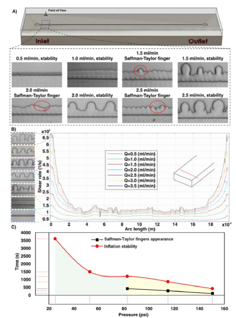
Figure 2. (A) Analyzing the Safman-Taylor fi ger criteria for the bonding quality in a microchannel versus various fl w rates. For fl w rates lower than 1.5ml/min, the Safman-Taylor fi gers do not appear, while for fl w rates more than 1.5ml/min, Safman-Taylor fi gers become discernible. (B) Shear rate distribution across a line parallel to the channel width. (C) Te more the pressure, the faster the creation of Safman-Taylor fi gers. In the green area, Safman-Taylor fi gers do not appear during the experiments. Also, the results show that there is not any evidence of channel burst or delamination during the bonding quality test.
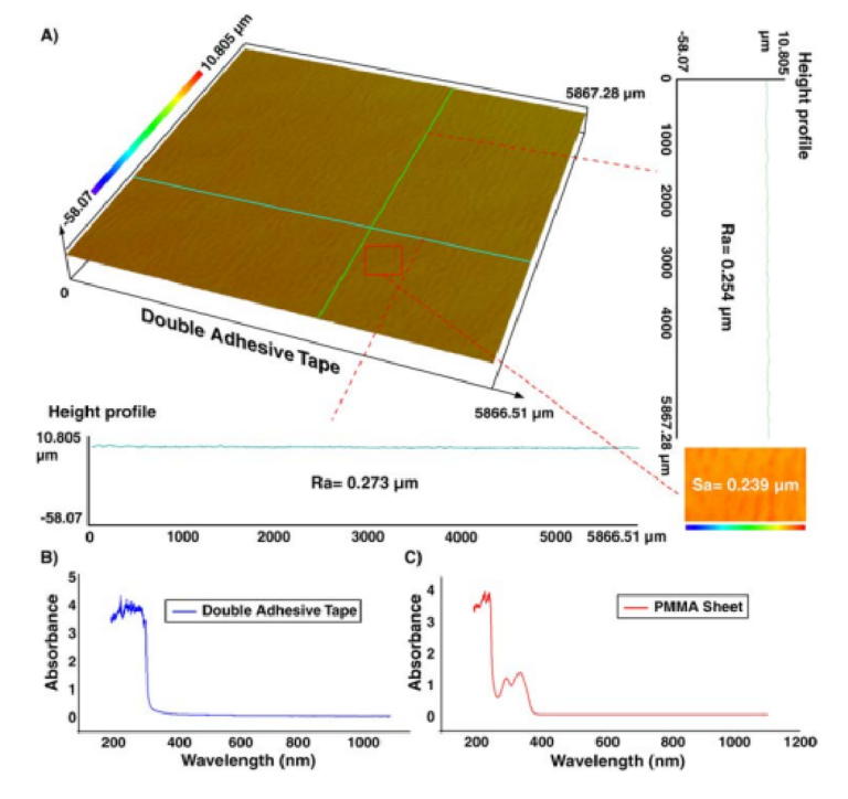
Figure 3. (A) Surface topography of the double-coated adhesive tape. Results in a vertical line (green line), horizontal line (blue line), or across an area (red rectangular) show that the tape has homogenous roughness with a nanometric value, which does not impose any interference on the channel performance. Te absorbance amount of (B) double-coated adhesive tape and (C) PMMA sheet, implying that these two materials are transparent for visible spectra range, and there is not any signifi ant absorption.
Sinusoidal and serpentine microchannel.
Inertial microfuidics in sinusoidal (curvilinear) microchannel has gained traction due to its improved focusing performance, the ability of massive parallelization, and small footprint. In the sinusoidal microchannel, the curvature direction changes in each loop, resulting in an intricate phenomenon that help in particle focusing. Indeed, by alternating the curvatures, the direction of Dean fl ws changes, and secondary fl ws may not reach a steady-state condition. Th s design was fi stly developed by Di Carlo in 2007 and its capability in wide ranges of Dean number ( / De = Re D R2 h , where Re is channel Re, Dh is characteristic length of channel, and R is the radius of channel curvature) was evaluated56. By assuming that Dean drag forces were balanced with shear gradient lift forces, his team proposed the ratio of inertial lift forces to Dean drag forces as F F L D / 2 = ra /Dh 2 3 (where r is radius of channel and a is particle diameter). Generally, if FL/FD ≫ 1, secondary fl ws do not afect particles, and if FL/FD ≪ 1, particles are entirely afected by secondary fl ws57. Th application of this microchannel was even expanded where it was used for high-throughput separation of micron and sub-micron bioparticles (cyanobacteria)58 and a microfuidic concentrator for harvesting of cyanobacteria59. In addition, in a comprehensive study, the design principle of curvilinear microchannels was investigated, and a map for various focusing phenomena was provided, based on F F/ ( ~ Re / ) De ( / a D ) f L D h L 2 2 3 where fL was approximated by Zhou and Papautsky21 as fL ~ 1/Re(Dh/a)2 60. Te dependency of curvature angle61 and various cell lines62 on the focusing positions was also evaluated. In order to showcase the adaptability of our method for fabrication of various inertial microfuidic devices, a curvilinear microchannel with rectangular cross-section (Fig. 5A) was designed, fabricated, and evaluated. Figure 5B reveals that 15 µm particles fi st occupied two focusing positions and by increasing the fl w rate, it reduced to a single focusing line across the channel (e.g., at 5th loop for fl w rate of 900µl/min (Fig. 5C)) which is consistent with the previously reported results60.
By altering the design of curvilinear to straight, serpentine microchannel with a square-wave pattern is created. Th s channel proves to have unique features for size-based particle focusing. Generally, particle focusing achieves when a/Dh > 0.07 and Rp~1. However, additional secondary fl ws in serpentine microchannel lead to focusing of particles with smaller diameters compared to those calculated by the above formula. Tese devices can beneft from parallelization along their vertical direction, thereby increasing their throughput. Tree focusing
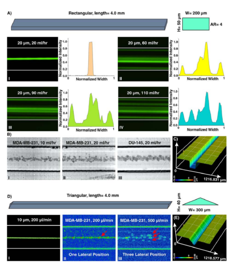
Figure 4. (A) Inertial microfuidics in a rectangular straight microchannel with height and width of 50 µm and 200 µm, respectively. I. At fi st, 20 µm particles occupy the center of the channel as their focusing position. Te intensity profle also illustrates that particles are focused at the center of the channel. II–IV. Later, looking at lateral position and intensity profles reveal that by increasing the fl w rate, side walls are added to the focusing position of the particles, and the focusing band of particles at center becomes wider. To extract these images, we have used “max intensity” feature from Fiji Sofware (https://fji.sc). (B) Te equilibrium position of MDA-MB-231 cells at fl w rates of I. 10ml/hr and II. 20ml/hr and III. DU-145 cells at fl w rate of 20ml/hr confi ms the single-line focusing of cells within the rectangular straight microchannel (from top view). (C) A surface proflometry of the rectangular cross-section which shows the rectangular profle of the microchannel. Results show that the channel has perfect shape and quality which is suitable for inertial microfuidics. (D) In triangular microchannel, particles fi st migrate to I. and II. one focusing position and then this increases to III. three separate points. Th s trend is similar to those reported in the literature14,53,54. Te results for MDA-MB-231 cells at fl w rate of 200 µl/min illustrate a single-line focusing position, and at fl w rate of 500 µl/min depict three focusing positions. (E) Surface proflometry of the triangular straight microchannel with height and width of 40 µm and 300 µm, respectively
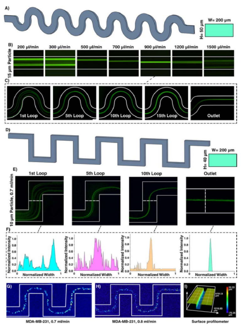
Figure 5. (A) Inertial microfuidics in a curvilinear microchannel with height and width of 50 and 200µm, respectively. (B) Te results show that the equilibrium position of particles depends on the fl w rate and has diferent focusing modes. Particles fi st focus at two equilibrium positions and then occupy just one focusing line. Eventually, by further increasing the fl w rate, Dean drag forces become dominant, resulting in defocusing of particles. Te trend is similar to that reported in the literature60. (C) 15µm particle migration throughout the channel for fl w rate of 900µl/min, demonstrating that particles are focused at the 5th loop. (D) Inertial microfuidics in a serpentine microchannel with height and width of 40 and 200µm, respectively. Te number of lateral positions depends on the applied fl w rate at the entrance of the channel. (E) Focusing behavior of 10µm particles at 0.7ml/min. (F) As intensity profle elucidates, at the 10th loop, particles reach the stable equilibrium position. Lateral migration of MDA-MB-231 cells at fl w rate of (G) 0.7ml/min and (H) 0.8ml/min shows a single-line focusing of these cells at the center of the channel. (I) Surface proflometry of the channel with rectangular cross-section with width and height of 200 and 50µm, which shows the accuracy and high-quality of the channels appropriate for inertial microfuidics.
patterns can be identifi d by increasing the input fl w rate, i.e., two-sided focusing, transition focusing, and central single-line focusing. If inertial efects dominate the secondary fl ws, particles occupy two lines near the walls. In contrast, dominance of secondary fl ws results in a single-line focusing at channel center. If these two efects have the same order, particles focus as a wide streak. Gaining the efciency of two-sided focusing for small particles and central focusing for big ones give us the opportunity of size-based particle separation. Based on the literature, a serpentine microchannel with cross-section of 40×200µm (H×W) and 15 loops was fabricated and used to showcase the focusing of 10 µm particles (Fig. 5D). In a straight channel with 40×200 µm (H×W) cross-section, a/Dh for 10 µm is 0.056, which is less than the focusing criteria (0.07); theoreically, these particles cannot focus in a straight microchannel. However, in the serpentine microchannel with the aid of secondary fl ws, 10 µm particles can effici tly be focused. Figure 5E elucidates that 10 µm particles at fow rate of 0.7ml/min can be focused at the center of channel at the 10th loop and occupy central equilibrium position at the outlet, which is consistent with the insets as normalized intensity profle of the particles (Fig. 5F). More importantly, the performance of device was tested with MDA-MB-231 cells (Fig. 5G,H), and the results are consistent with those reported in the literature63. Te surface proflometry of the channel cross-section is also provided in Fig. 5I, indicating the high-accuracy of the proposed method for fabrication of inertial microfuidic devices.
Spiral microchannel.
Spiral defi es as a curve winding around a center point with continuous decreasing or increasing manner. When fl w passes the curvature, velocity mismatch occurs in the curve section of the channel, resulting in the generation of secondary fl ws. In inertial microfuidics, spiral microchannel has progressed signifcantly, and nowadays, most of the particle/cell separations are performed using these microchannels64. De is used for the characterization of secondary fows within the channel. Intuitively, smaller channel curvature or larger channel size or Re leads to higher De, thereby imposing stronger secondary fl ws within the channel. For a given De, average transverse Dean velocity (UDe=1.84×10⁻⁴ De1.63) and Dean drag force = = πµ α π . × µ α − . ( 3 F U 5 4 10 De ) D De 4 1 63 can be identifi d. However, the exact behavior of particle migration at the downstream of the fuid was not thoroughly investigated, and all results are based on experimental data. Te most appealing feature of spiral inertial microfuidics is its high-throughput where 2100 particles per second can be processed9 . Particle sorting is one of the most signifcant applications of spiral microfuidics. Previously, the potential of a rectangular spiral microchannel for continuous and simultaneous isolation of 10, 15, and 20µm based on soflithography was investigated (Fig. 6AI) 65. Dean fl w dynamics for a low-aspect-ratio rectangular spiral microchannel was also thoroughly explored66. Beyond a simple rectangular spiral microchannel, various geometry modifcations for regulation of Dean forces and performance enhancement of the device have been proposed. Beneftting from micromilling (Fig. 6AII), trapezoidal spiral microchannels illustrate promising results in redistribution of lateral focusing positions of particles appropriate for size-based particle separation. In these channels, smaller particles focus along the outer wall, whereas larger ones migrate toward the inner wall67. Th s superior advantage has been widely investigated by our group, among other groups, for circulating tumor cell (CTC) and circulating fetal trophoblasts (CFT) isolation19,68, blood plasma separation69, isolation of microcarriers from mesenchymal stem cells70,71, microalgae separation72, and synchronizing C. elegans73. Also, multiplexing using stack of attached PDMS layers to boost the throughput is illustrated previously69,74. However, most of the aforementioned applications are just doable by utilizing cleanroom facilities or employing conventional micromachining (e.g., metal machining or laser cutting) for the fabrication of microchannel. Besides, micromachining has its own limitations such as inability to make sharp corners or difculty in making spiral loops close to each other. Tese challenges highlight an unmet need for the fabrication of spiral microchannels using a versatile method which is robust and can surmount aforementioned issues.
As a showcase of the versatility of our proposed method, we have fabricated a spiral microchannel with trapezoidal cross-section with a width of 600 µm and heights of 80 and 130 µm. Tese results are then put aside a PDMS chip with similar dimensions, and the data is provided in ESI (Fig. S5). Despite all progress in spiral inertial microfuidics, there is not any report of a spiral with cross-sections rather than rectangular or trapezoidal. In other words, a huge amount of potential remains intact to study spiral microchannels with diferent cross-sections such as triangular (Fig. 6AIII). For this aim, for the fi st time, we have fabricated a spiral microchannel with right-angled triangular cross-section (as schematically shown in Fig. 6B) where the width and height are 600 and 210µm, respectively. As the results are illustrated in Fig. 6C, there is a tight band focusing for particles larger than 10 µm, which is suitable for high throughput fl w cytometry applications where single line focusing is desired. Also, we observed double-band focusing behavior for 20µm particles at fl w rate of ≥4ml/min. Te dimensions (Fig. 6D) and channel cross-section (Fig. 6E) show the accuracy of the proposed method the for fabrication of right-angled triangular spiral microchannel (check Fig. S6 for contraction-expansion array microchannel results). Tese results illustrate the flex bility of this method where a complex cross-section can be fabricated in less than two hours with high robustness and stability. Our results hold promise for leveraging the potential of additive manufacturing for the fabrication of inertial microfuidic devices, which is more challenging using conventional microfabrication methods (see Section S6 for multiplexing of 3D printed inertial microfuidic devices).
Cellular studies.
PDMS-made inertial microfuidic devices have been widely used for the cell separation using biological samples such as blood and urine. While PDMS is proven to be a biocompatible material with minimum side efects on cells, we have tested the 3D printed devices using DU145 cells, assessing their viability and functionality post-separation. Te collected cells from the device outlet were cultured back into a petri dish for 5 days, showing similar morphological features to the control group as shown in Fig. 7A,B. Te fl w cytometry tests (Fig. 7C) showed that the viability of the cells was not compromised during the operation using 3D printed devices. Te real-time PCR analysis was utilised to assess the expression of genes related to the general activities and stress responses in both treated and untreated cells (Fig. 7D). Te similar expression level of GAPDH and CDKN2A confi med that neither cellular metabolism nor cell cycle progression were afected afer processing
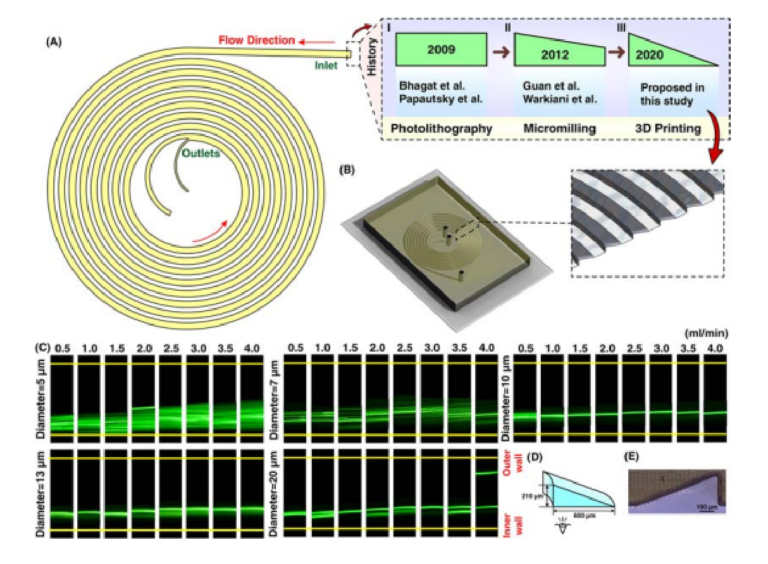
Figure 6. (A) Illustration of a spiral microchannel where the fuid direction is from outside to inside. I. Firstly, several groups (e.g., Bhagat et al. 9 , Papautsky et al. 66,77, etc.) have shown the capability of rectangular spiral microfuidics for such applications as fl w cytometry or microparticle/cell separation. Te fabrication of these devices was based on photolithography. II. Gaining the effici cy of micromilling, many groups (e.g., Guan et al. 67, Warkiani et al. 20, etc.) made an attempt to get the advantage of trapezoidal spiral microchannel for particle/cell fltration and fractionation. III. In this study, for the fi st time, we have shown the fabrication of a right-angled triangular spiral microchannel with the aid of additive manufacturing. (B) Schematic illustration of the microchannel where the inset shows the cross-section of the microchannel. (C) Results reveal that for particles larger than 10 µm, a tight focusing band appears at the outlet of the channel. Also, for larger particles at high fl w rates (i.e., 4 ml/min) double-band focusing appears. (D) dimensions of the right-angled triangular spiral microchannel where the inner wall is 210 µm and the width is 600 µm. Te hydraulic diameter of this channel is similar to a spiral with a trapezoidal cross-section and the dimension of 80×130×600 µm. (E) Illustration of a right-angled triangular cross-section, which shows the accuracy of the fabrication process.
through the microchannels. Also, there are no signifi ant changes in the expression of TXNIP and MAPK14, which are two well-known regulators of cellular stress. In all, the 3D-printed inertial microfuidic device does not alter the cell activity and is safe to be used in biological assays.
Conclusion
In this study, we have showcased a robust and versatile workfl w for the manufacturing of inertial microfuidic devices for both laboratory experiments and industrial applications. Te proposed method involves 3D-direct printing of a channel with the desired structure and geometry via a high-resolution DLP/SLA 3D printer. Our approach relies on the bonding of 3D-printed devices (i.e., with high-quality surface fin sh) to a transparent PMMA sheet via a double-coated pressure-sensitive adhesive tape. Given the great transparency of PMMA layer, these devices can be utilised in bright fi ld, phase contrast, fuorescent, or high-speed microscopy. Te bonding quality was evaluated by Safman-Taylor fi ger criterion, and the results showed that the device is capable of withstanding pressure as high as 150psi (nearly triple of the value reported for PDMS). Te versatility of this method allowed us to fabricate and evaluate a plethora of existing inertial microfuidic devices as exemplifi d for fabrication of straight, spiral, serpentine, curvilinear, and contraction-expansion arrays microchannels. Te total time frame, from designing a part to starting an experiment, takes less than two hours, allowing multiple experiments in a single day. Also, for the fi st time, we have fabricated and examined a new inertial microfuidic device, i.e., spiral microchannel with right-angled triangular cross-section which is theoretically impossible to fabricate using photolithography. We believe that the proposed workfl w will provide inertial microfuidic devices within the reach of any research groups involving in particle/cell manipulation without strong microfabrication background.