Development of highly accurate 3D printed artificial cochlea model
Filip Hrncirik, Iwan V. Roberts , Chloe Swords, Manohar L. Bance
During cochlear implant (CI) insertion, the mechanical trauma causes a loss of residual hearing in up to 50% of implantations. [1-3] This can severely limit CI performance through neural degeneration and fibrosis caused by acute mechanical damage and chronic inflammation. Present methods enabling detailed characterisation of the implant-cochlea interactions involve animal or cadaveric testing. [4-5] Limitations: difficult to source, instrument, and measure § Cannot be systematically varied in shape and size parameters Aim: Create highly accurate and optically clear 3D printed cochleae at a realistic scale within the range of shapes and sizes seen in humans and measure insertion forces in them.
We kindly thank the researchers at University of Cambridge for this collaboration, and for sharing the results obtained with their system.
Methods
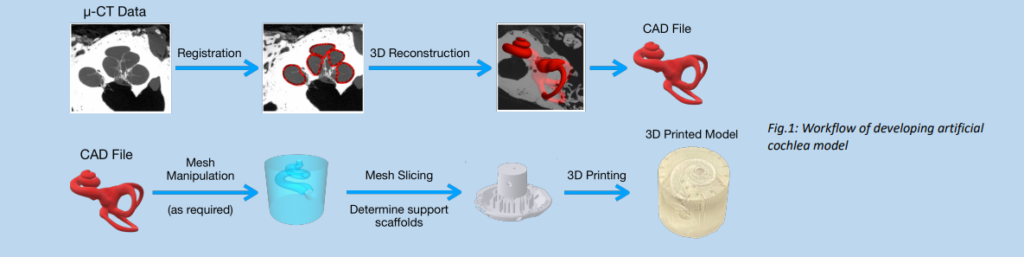
Human cadaveric temporal bones were imaged using micro-computerised tomography (microCT) scanner and reconstructed to produce computer-aided design (CAD) files.
Initial screening – a variety of 3D printing technologies were evaluated using an optical microscope to fabricate an accurate artificial cochlea model focusing on the print smoothness and geometric accuracy. ﹒Multi-jet printing (MJP) – 3D Systems ﹒Digital light processing (DLP) – Asiga and Cadworks3D ﹒Continuous digital light processing (cDLP) – EnvisionTEC ﹒Low force stereolithography (LFS) – Formlabs Form 3
In-depth assessment of performance with Scanning Electron Microscopy (SEM) and micro-computed tomography (microCT) ﹒Nominal-actual analysis – observe the deviation of artificial cochlea models and the original 3D reconstruction of cadaveric microCT ﹒Six duplicates for statistical analysis
﹒ Optimised post-processing for high optical transparency of the printed models. Three techniques were examined: 1) recommended by the manufacturer, 2) acrylic coating, 3) resin coating
﹒ Insertion platform – 1-axis load cell with a camera located above the model synchronised with the stepper motor for slow controllable insertions.
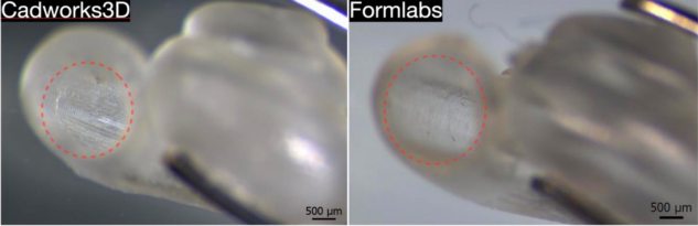
Initial screening ﹒DLP (Cadworks3D) and LFS (Formlabs Form3) 3D printing technologies demonstrated superior performance with excellent surface smoothness and geometric accuracy
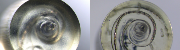
Fig.2: Analysis with optical microscope. Left – model printed with DLP; Right – printed with LFS
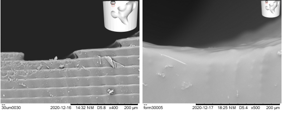
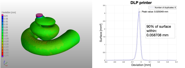
In-depth assessment of DLP and LFS printers ﹒SEM analysis revealed the variations between different printing settings of DLP technology (step-like finish) and a very smooth finish achieved by LFS technology. ﹒MicroCT with nominal-actual analysis showed that 90% of the surface is within 58 μm of deviation with prints printed with DLP technology
Fig.3: SEM analysis. Left – model printed with DLP; Right – printed with LFS
Fig.4: Left – Visualisation of deviation; Right – Chart showing that 90% of the surface is within 58 μm of deviation; Both images show results of DLP printing
Post-processing of the prints ﹒Post-processing was optimised with the use of acrylic coating ﹒The coating did not have a significant impact on the print deviations.
Fig.5: SEM analysis. Left – model printed with DLP; Right – printed with LFS
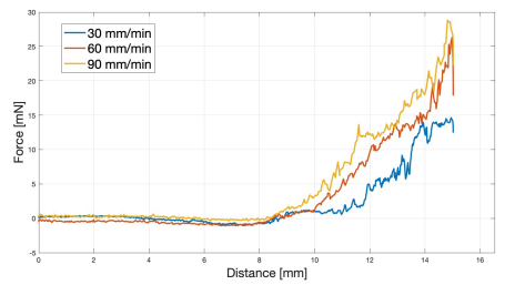
Insertion setup – preliminary data ﹒Higher insertion speeds result in higher insertion forces ﹒Early experiments show high dependence on the round window placement; however, more investigation is needed
Fig.6: Measurement of insertion forces with 3 insertion speeds
Results
The production of highly accurate, optically clear models of the human cochlea using DLP and LFS 3D printing technologies is presented alongside the characterisation of insertion force according to different parameters. These models provide a good base for evaluating the insertion forces and behaviour of the implant during implantation.
References [1] Jia H, Wang J, François F, Uziel A, Puel J-L, Venail F (2013) Molecular and Cellular Mechanisms of Loss of Residual Hearing after Cochlear Implantation. Ann Otol Rhinol Laryngol 122:33–39 . https://doi.org/10.1177/000348941312200107 [2] Zanetti D, Nassif N Factors affecting residual hearing preservation in cochlear implantation. 9 [3] Eshraghi AA, Ahmed J, Krysiak E, Ila K, Ashman P, Telischi FF, Angeli S, Prentiss S, Martinez D, Valendia S Clinical, surgical, and electrical factors impacting residual hearing in cochlear implant surgery. 6 [4] Claussen AD, Quevedo RV, Mostaert B, Kirk JR, Dueck WF, Hansen MR (2019) A mouse model of cochlear implantation with chronic electric stimulation. PLOS ONE 14:e0215407 . https://doi.org/10.1371/journal.pone.0215407 [5] Kretzmer EA, Meltzer NE, Haenggeli C-A, Ryugo DK (2004) An Animal Model for Cochlear Implants. Arch Otolaryngol Head Neck Surg 130:499–508 . https://doi.org/10.1001/archotol.130.5.499